The setup consists of several PCBs: two boards for the steering wired wheel remote, two for expansion board and one for the microphone. All of them were made by hand using a thermo-transfer method and hand-soldered. In this post I’ll go into details of board schematics, manufacturing process and end results.
Parts:
Expansion Board PCBs
The main component of the project - expansion board. It has the MCU, thermometer and display connectors, and last, but not least, digital potentiometer that generates a signal for the radio unit. The heart of the board is ATmega88 microcontroller - an 8-bit processor with 12-bit Analog/Digital Converter, hardware I2C (TWI) and SPI support, and more than enough GPIO pins.
List of peripherals connected to the board:
- Wired Remote - through build-in ADC
- DS18B20 - through GPIO pin
- SSD1306 Display Driver - through I2C (during software design process, turned out that this bus wasn’t the best choice)
- MCP42100 Digital Potentiometer - communication via SPI / signal output via 2,5 mm Jack socket (that wasn’t the best choice either - it is a real pain to hand-solder male plug)
- UART output (for debugging purposes) - through GPIO pins
In addition, for the sake of stability, MCU is clocked by external 4 MHz crystal oscillator connected to XTAL pins.
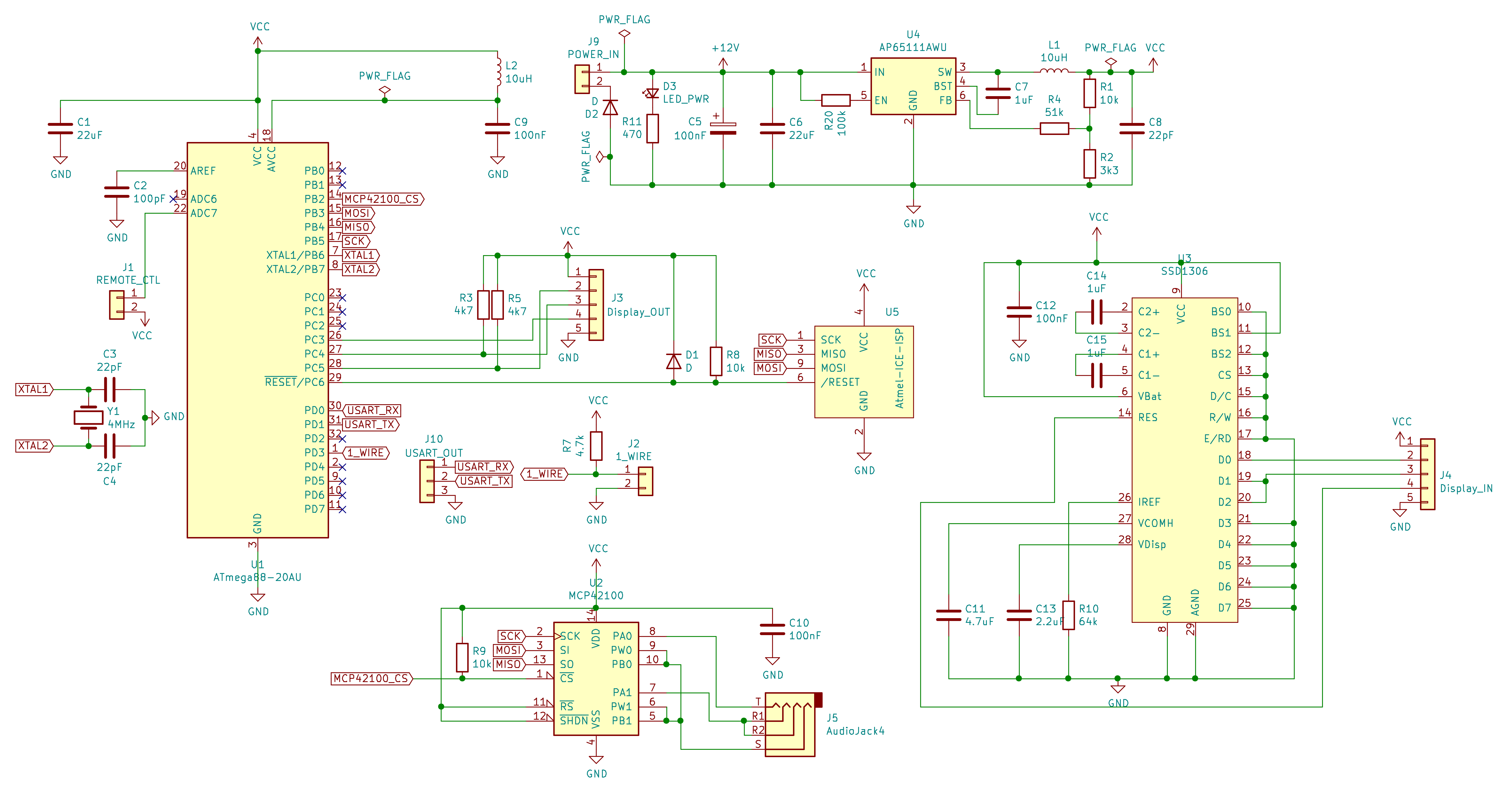 Schematic
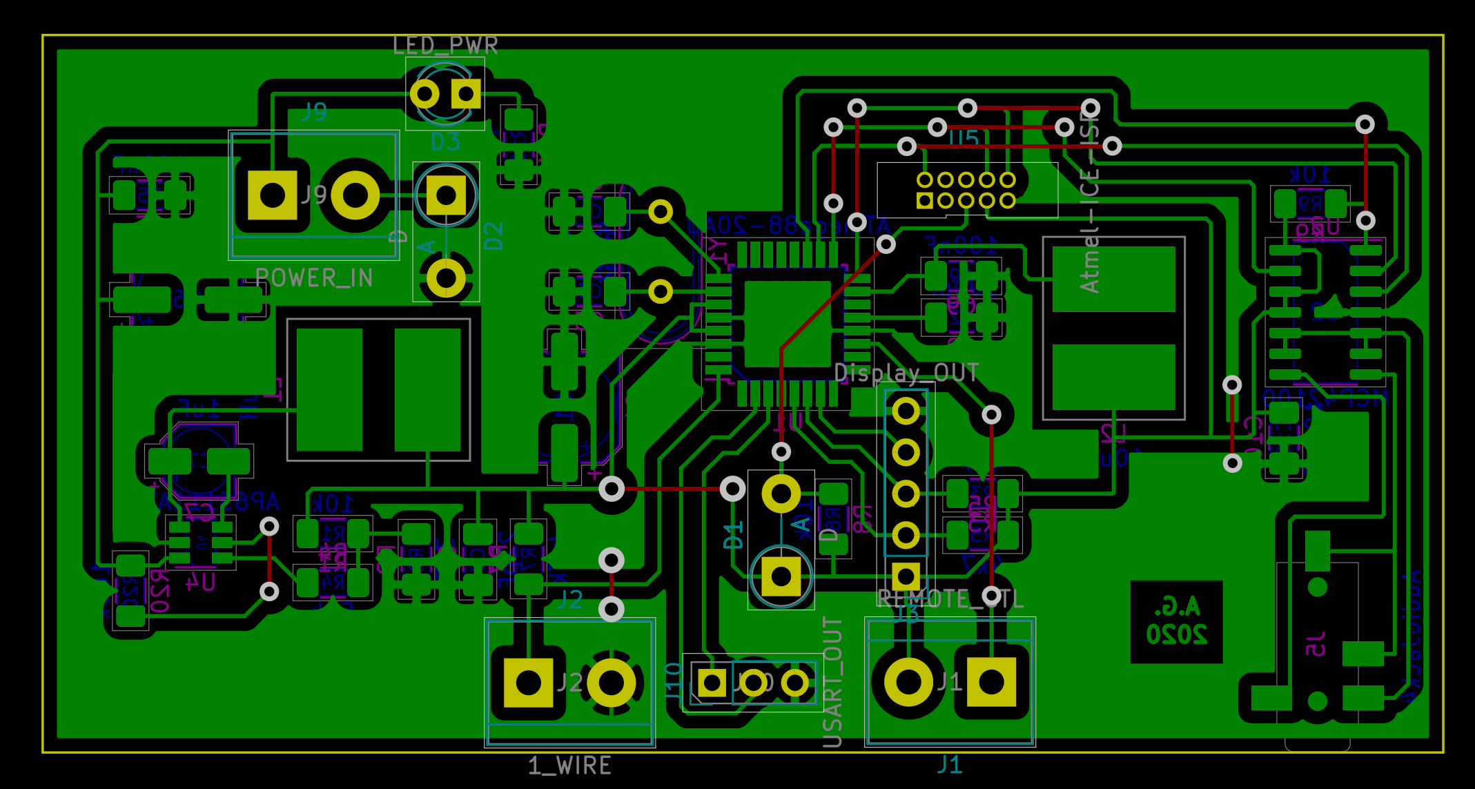 PCB
PCB
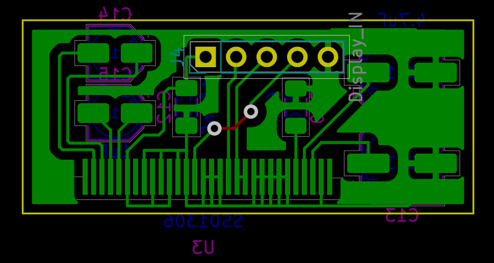 OLED Display PCB
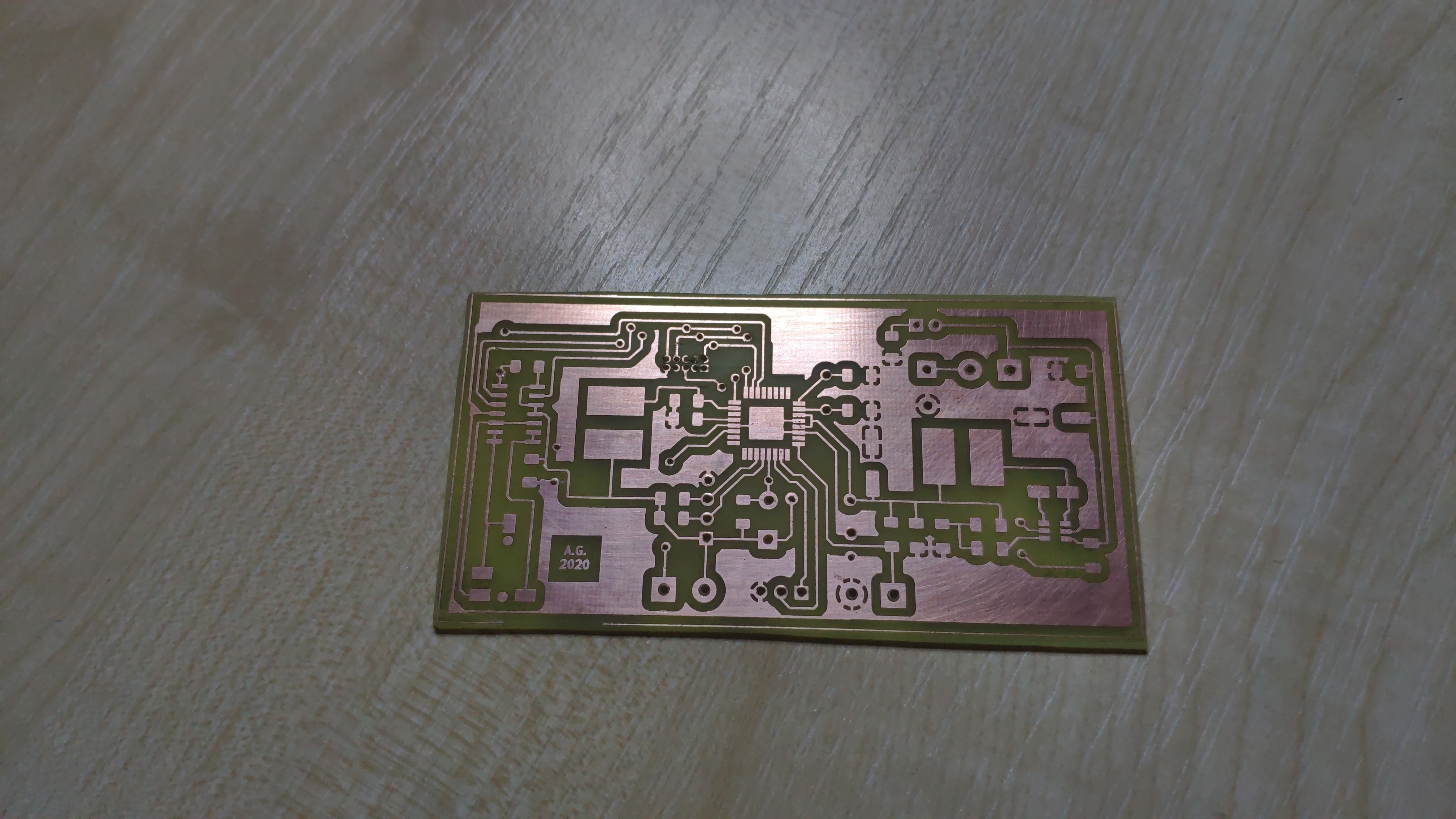 Expansion Board PCB after etching and drilling
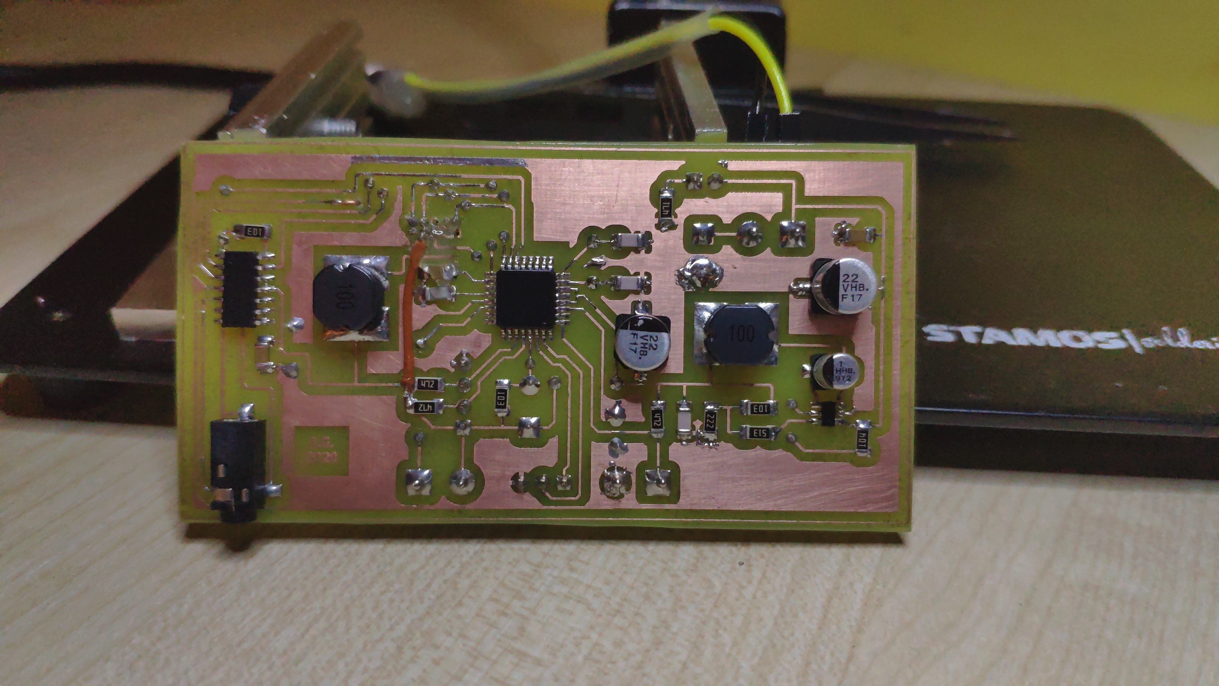 Expansion Board bottom
 Expansion Board top
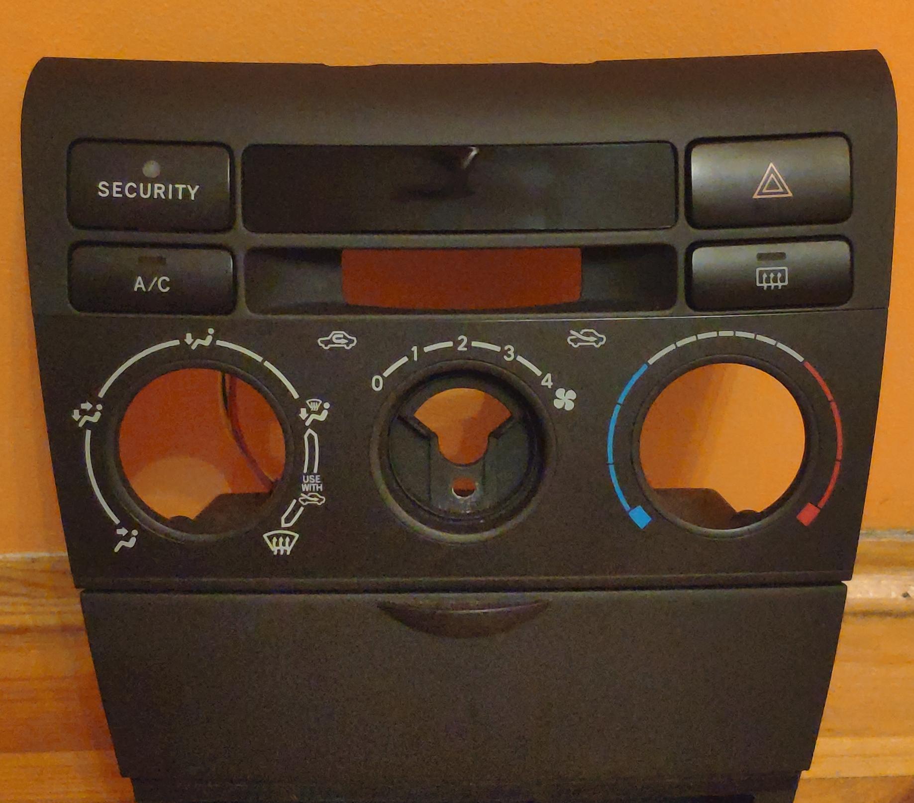
Expansion Board is split into two PCBs - one for main components and another for OLED display. That’s because of size constraints of the front panel, where display was placed. Conveniently Toyota designed a black plastic strip in the panel, that doesn’t serve any purpose except decorative touch. As I wanted to put the display in visible, yet discrete place, that strip was a perfect place for it. Because it isn’t transparent, I needed to get creative - I ordered semi-transparent smoked piece of acrylic glass (plexiglass), heated it to bend it so it would fit the curve of original strip and sanded the plexiglass piece to fit the shape of the strip.
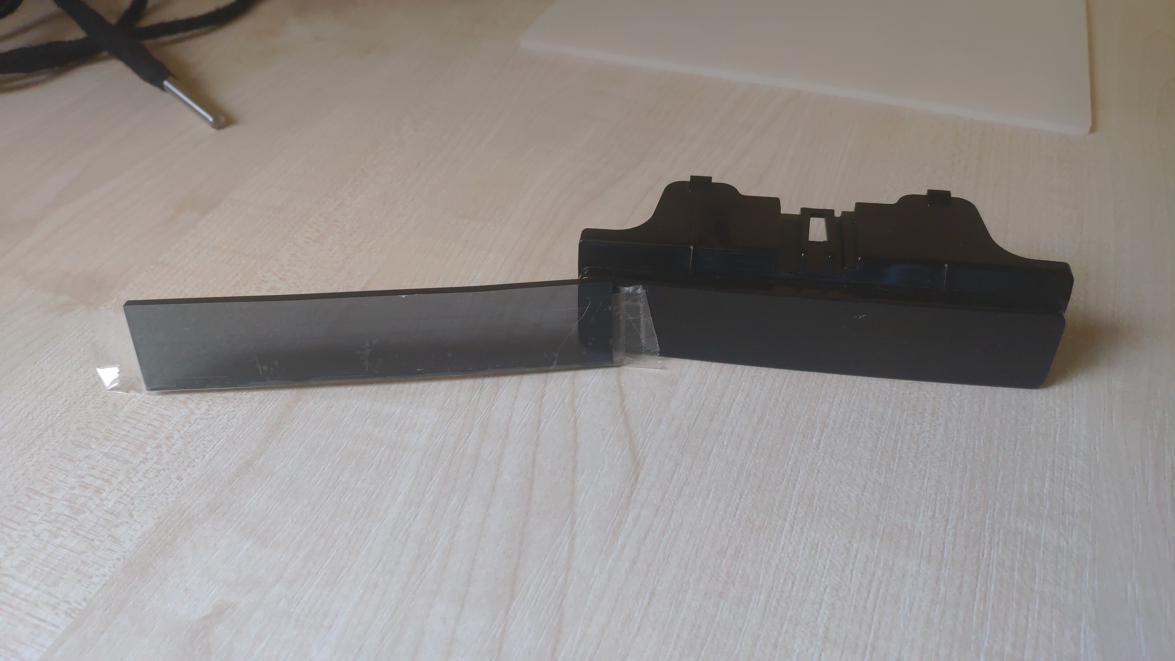 Plexiglass before refinement - original plastic strip untouched
 Plexiglass attached to the strip with double-sided tape, edges sanded to fit original shape
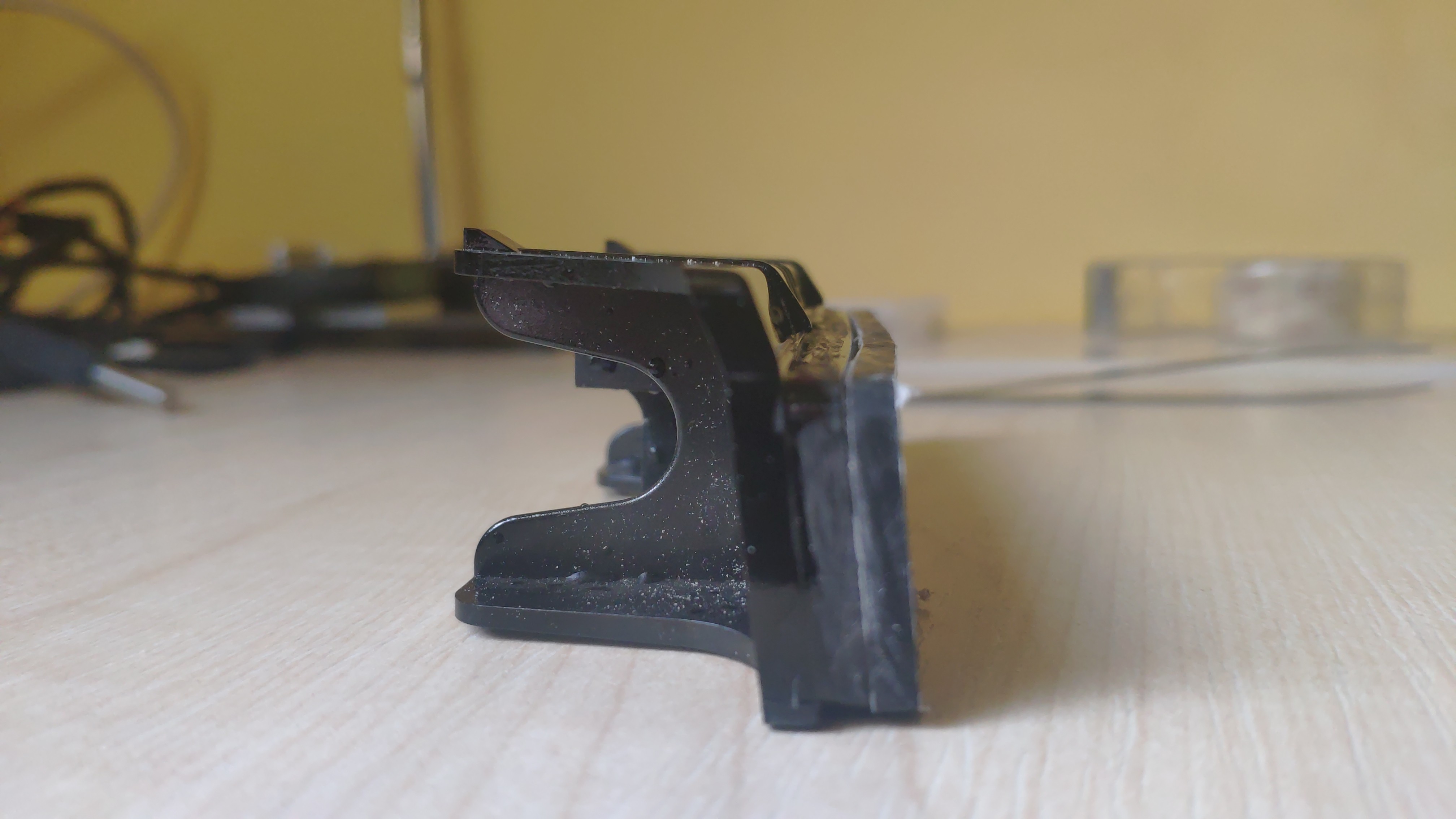 Look at the curve of the strip
 Strip front removed - ready to be replaced with plexiglass
 Most of the plexiglass will be painted with black spray - only visible area will be for the display
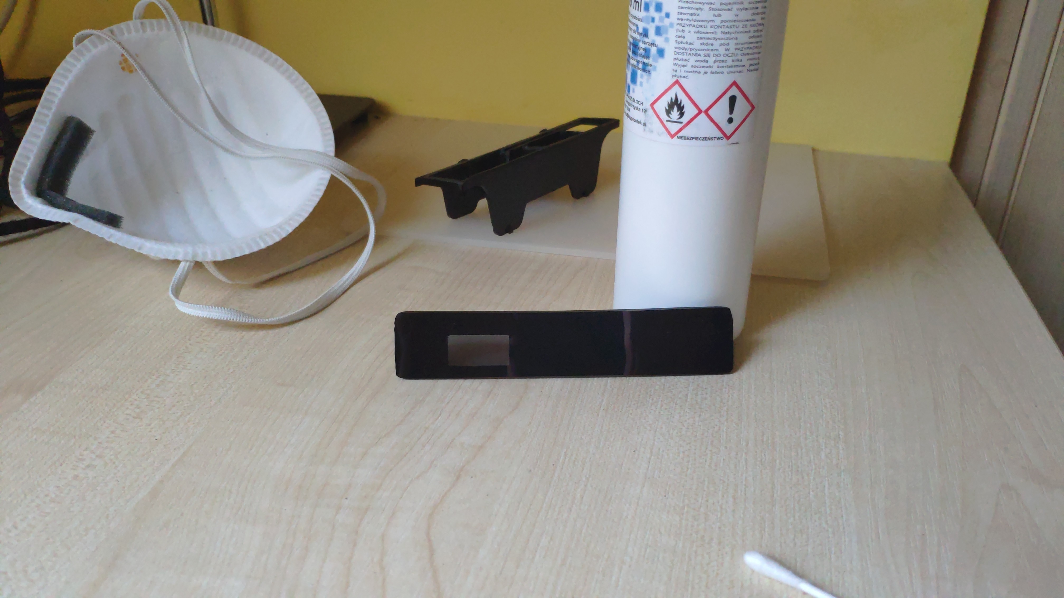 Plexiglass strip painted - some edges need refining, but small imperfections won't be very noticeable when display will be in place
 Plexiglass replacement mounted in front panel
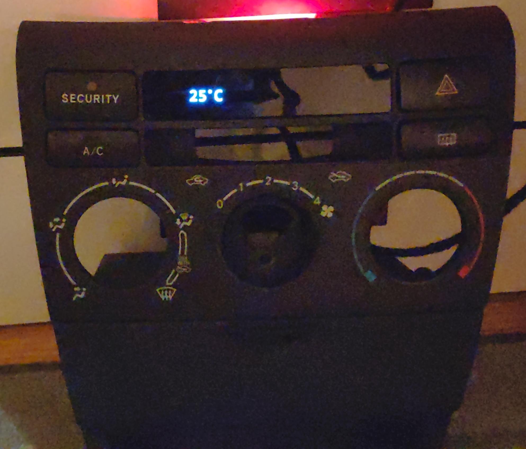 Display in place and working - poor photo quality due to bad light...
Although the first prototype board became the final board, during software development I discovered a few hardware bugs I needed to work around:
ATMEL-ICE and VCC bug
Turns out that Atmel’s programmer cannot flash the chip if VCC isn’t hooked up to ISP cable. For safety measures I left the VCC pin floating and after soldering essential components (voltage regulator, MCU and XTAL) I couldn’t figure out why programmer can’t communicate with the device. Hopefully Atmel Studio gave me a hint - while trying to communicate with the chip, GUI also shows current board voltage. Since VCC was floating, it was giving me around 0,5 V on the Atmel Sutdio side, while multimeter was showing 3,7 V on the board. In order to prove my suspicions, I soldered a wire between ISP’s VCC pin and board’s VCC line - and just like that I could flash the MCU.
MCP42100 rheostat in shutdown mode bug
Digital POT can work in two modes - rheostat, where it’s a 2-pin device and potentiometer where it’s a 3-pin device. For the purpose of the project, the first mode is needed. As documentation states, in order to get into this mode, one should connect the wiper to one of remaining terminals (A or B). Unfortunately the documentation doesn’t explicitly says that there is a difference between these two types of connection (Wiper -> A or Wiper -> B).
The shutdown mode is described as follows: “The shutdown command allows the user to put the application circuit into a power-saving mode. In this mode, the A terminal is open-circuited and the B and W terminals are shorted together.”. In shutdown mode, when A terminal is connected to Wiper, Wiper is also connected to B. In effect A and B are closed circuit with a small resistance between them (equal to Wiper resistance). Since the radio expects a signal that is toggled on and off with different path resistance, this type of connection just not gonna work - and I found it out the hard way. Just by a happy coincidence, I routed Wiper tracks in a way that I was able to cut them with a knife and solder it to the other terminal, effectively fixing the problem.
Steering Wheel Wired Remote PCBs
The stock wired remote is a two-piece board - each containing three buttons and backlight LEDs. It has a 6-pin, 2,54 mm pitch male connector with VCC, GND, TX and RX signals and ICs that are responsible for reading button states and transforming them into AVC-LAN messages. When remote has connectivity with the AVC-LAN bus and dashboard illumination is on, ICs control the remote backlight.
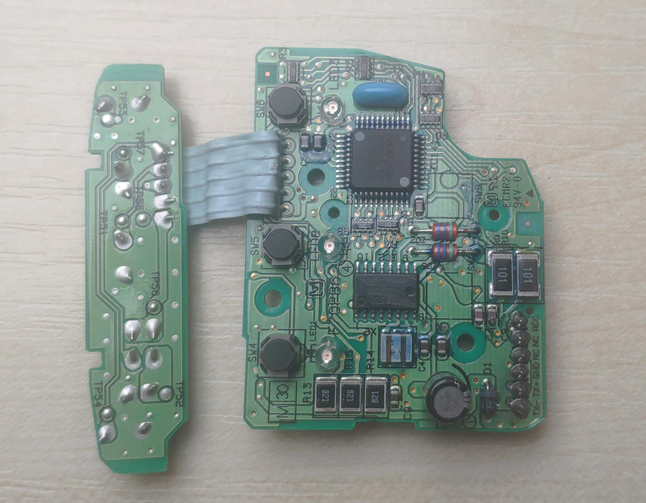 Stock Wired Remote PCBs
Since I didn’t need all that, I measured the boards and designed a replacements so that remote could have analog buttons with backlight. Fortunately 4 signal lines were enough to make it work - VCC and GND are needed anyway, I reused remaining two lines for Analog Out and Backlight signals. Schematic is dead simple - wired remote is basically a resistor ladder with six buttons and LED backlight, spread across two boards.
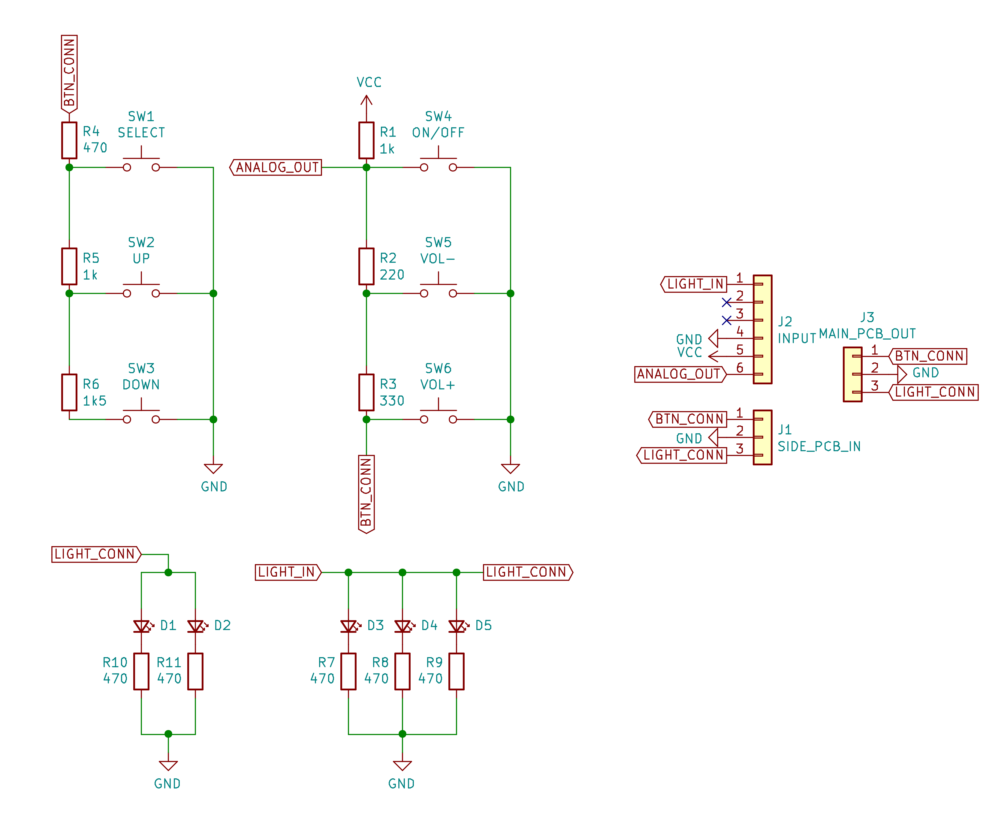 Schematic
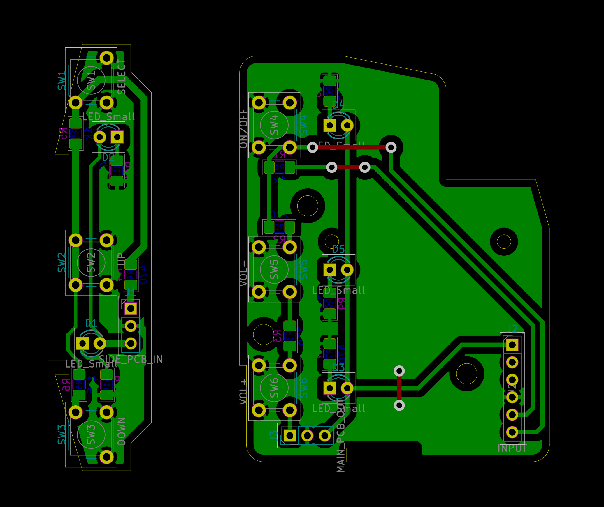 PCB
PCB
PCB is designed for standard tactile switches, but they seemed too loud, so I changed the buttons after making a PCB using a wire through existing holes and a bit of soldering hacking (nice and quiet buttons are SMD components). Below are real photos from the process of making a PCB and end result.
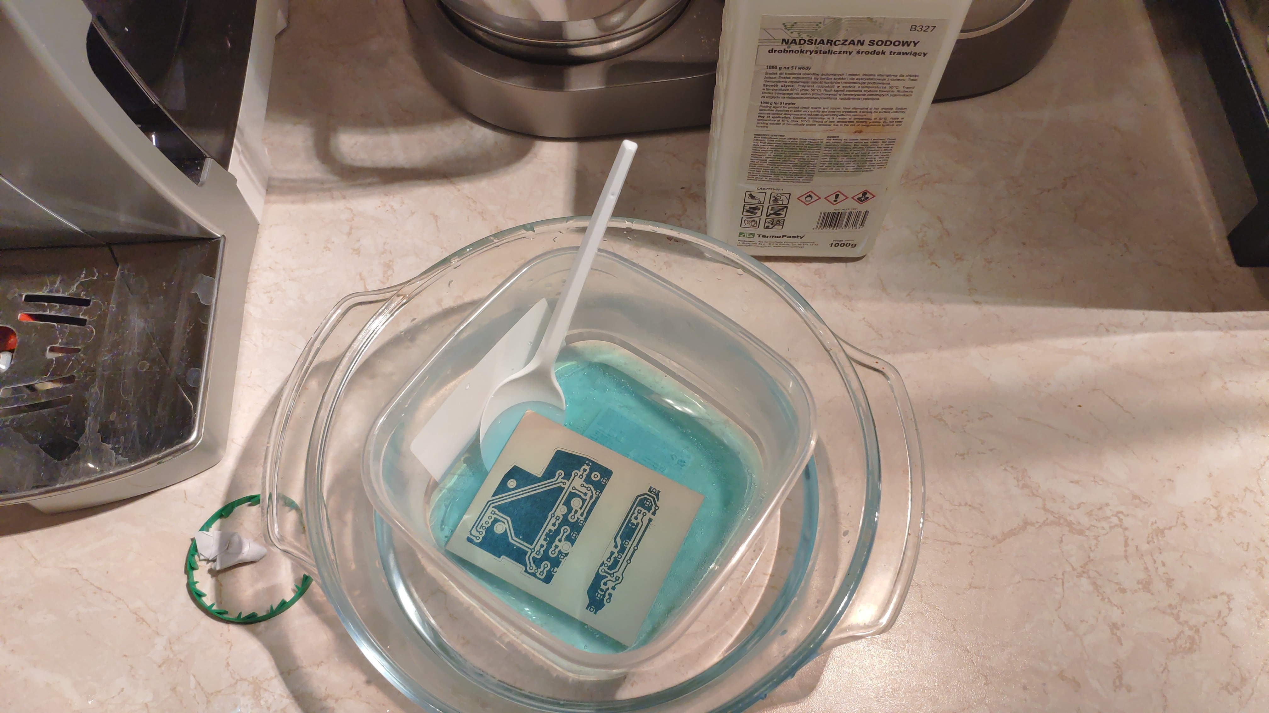 Etching PCB in sodium persulfate solution
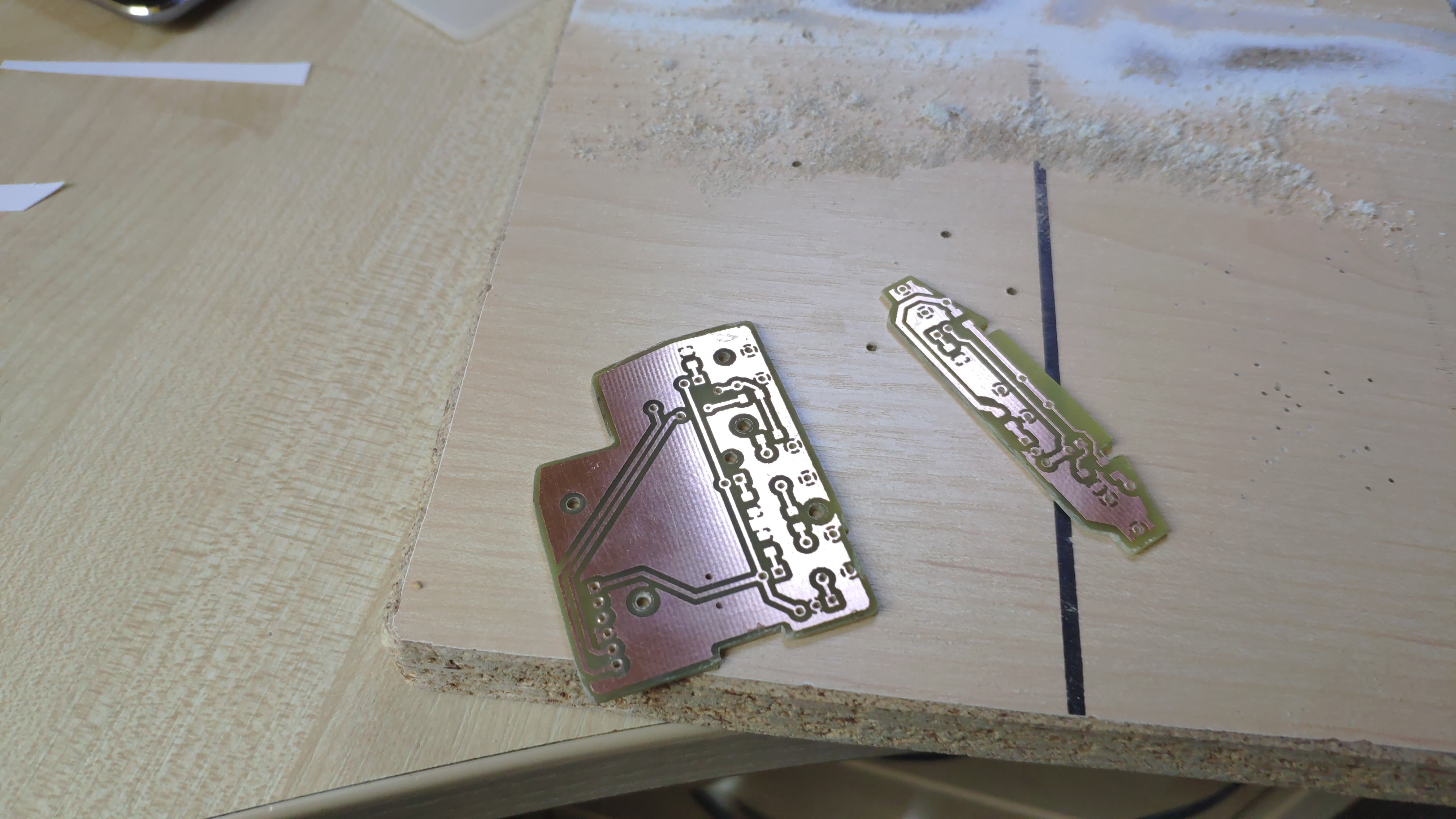
 Result of etching - circuit mask cleared. You may notice some small imperfections on copper - I made etching solution too warm, so the process got too violent and solution got through the mask
 PCB cut to final shape with drilled through holes
 Final boards
For connecting the remote with the expansion board, I used existing wires behind the steering wheel. To not mess up with ECU I needed to cut off existing lines, patch and extend them with a new set of wires, then put them in convenient place where I could reach the expansion board - luckily there’s plenty of room behind the dashboard.
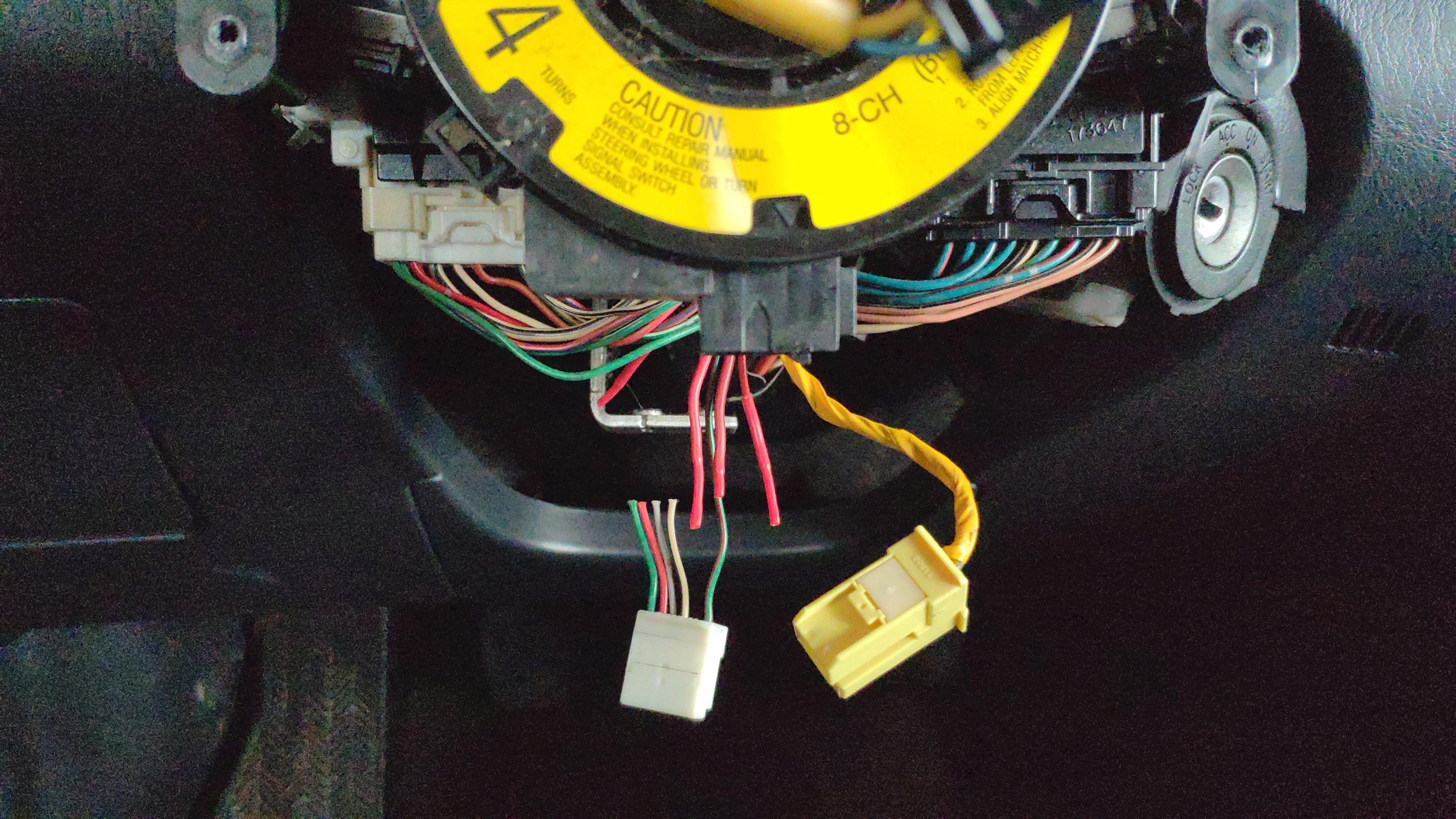 Stock connector with relevant lines cut off
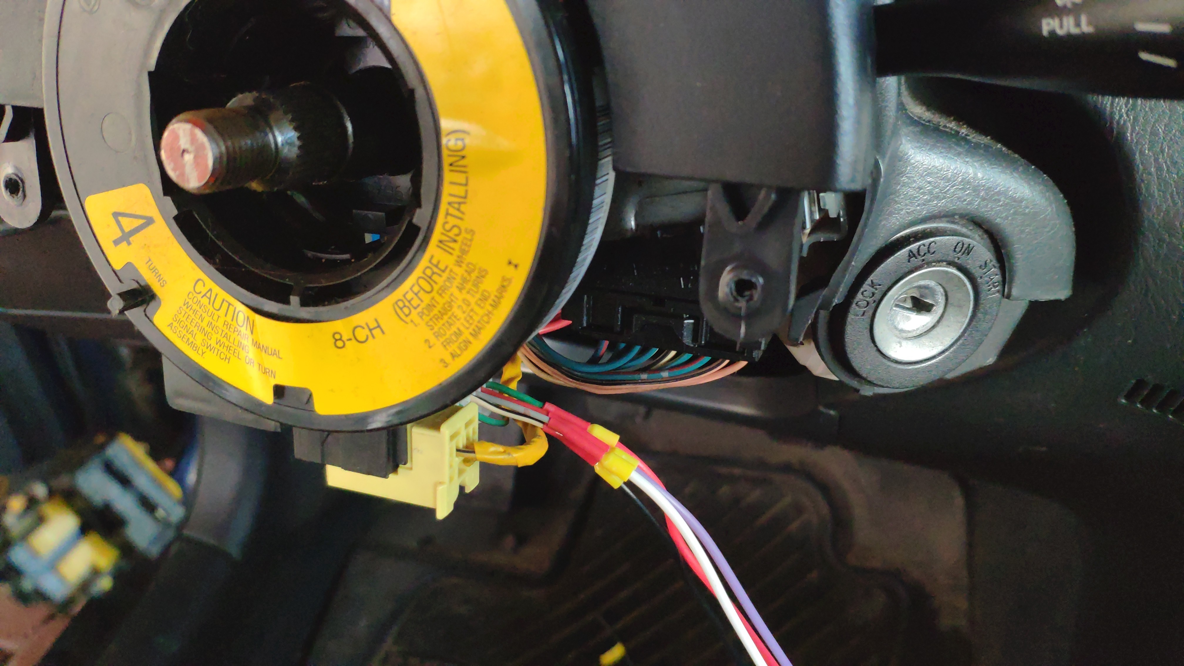 Patched connector with extension wires
 Wire extensions, isolated and labeled
Microphone hack
Since radio unit doesn’t provide auxiliary microphone input jack, I created a PCB where I placed a new microphone (plus I picked one with variable gain and set it to around 10 dB). The trick is radio’s microphone is an SMD component and there are no obvious pins I could tap into to get the signal in from external components. The only way to get around it was to desolder old microphone and put wires with a 3-pin connector at the end that would be available outside of radio’s case. Once that was done, I mounted replacement microphone behind dash panel, hooked up wires and voila - instead of talking to the radio, I can talk directly to the microphone in front of me.
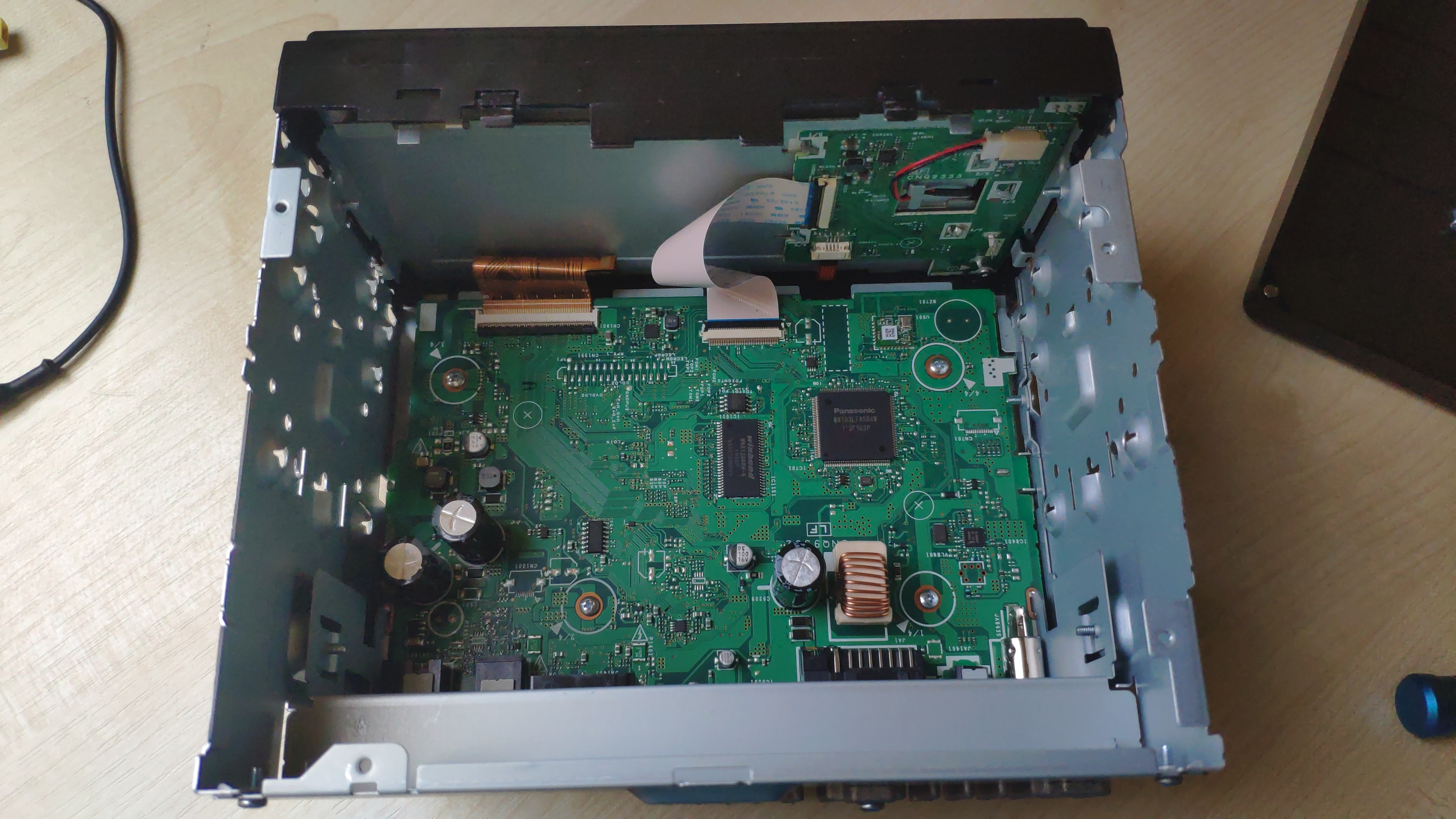 View of radio internals, microphone is on the front panel
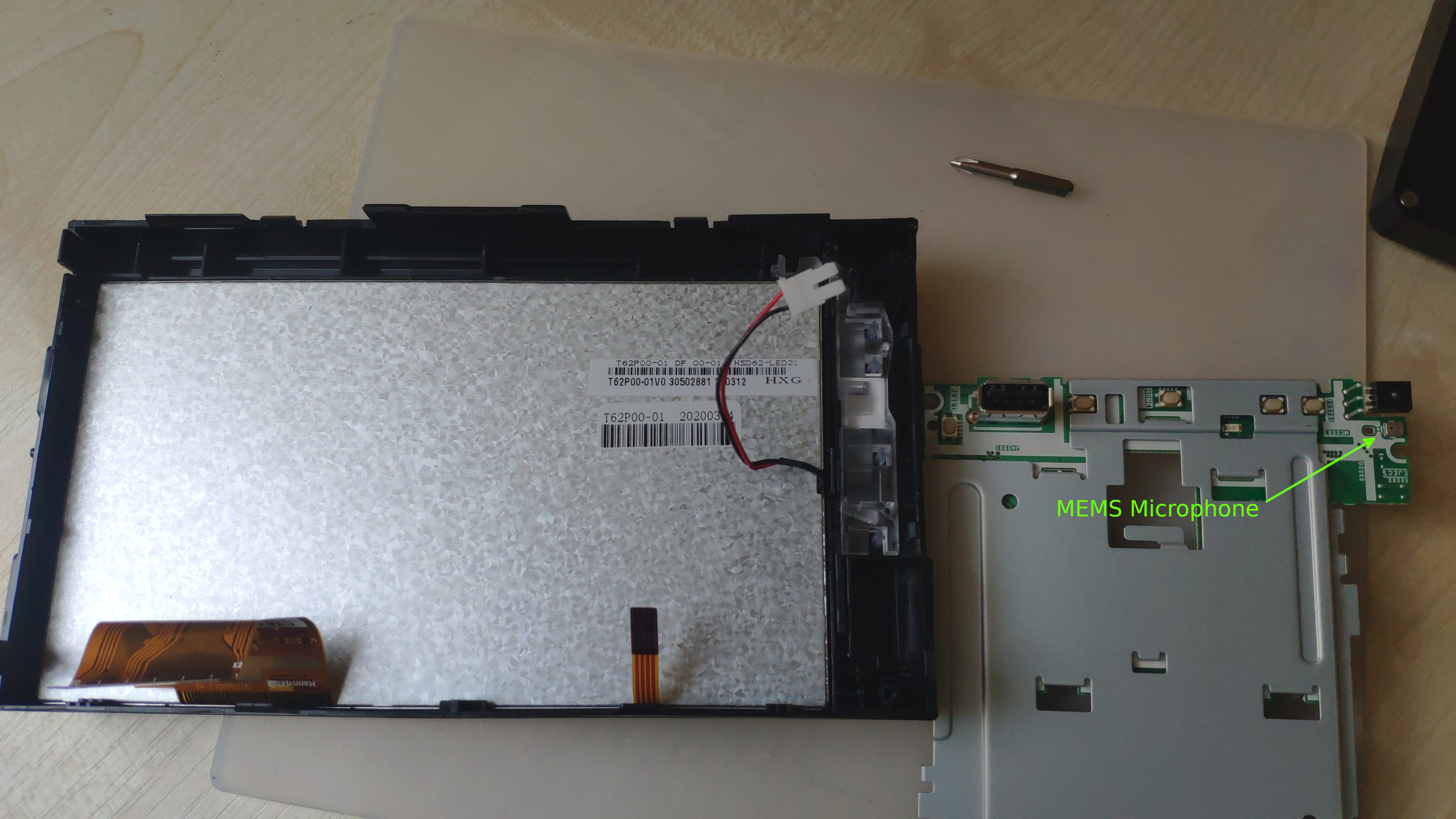 Front panel disassembled, microphone is an SMD component
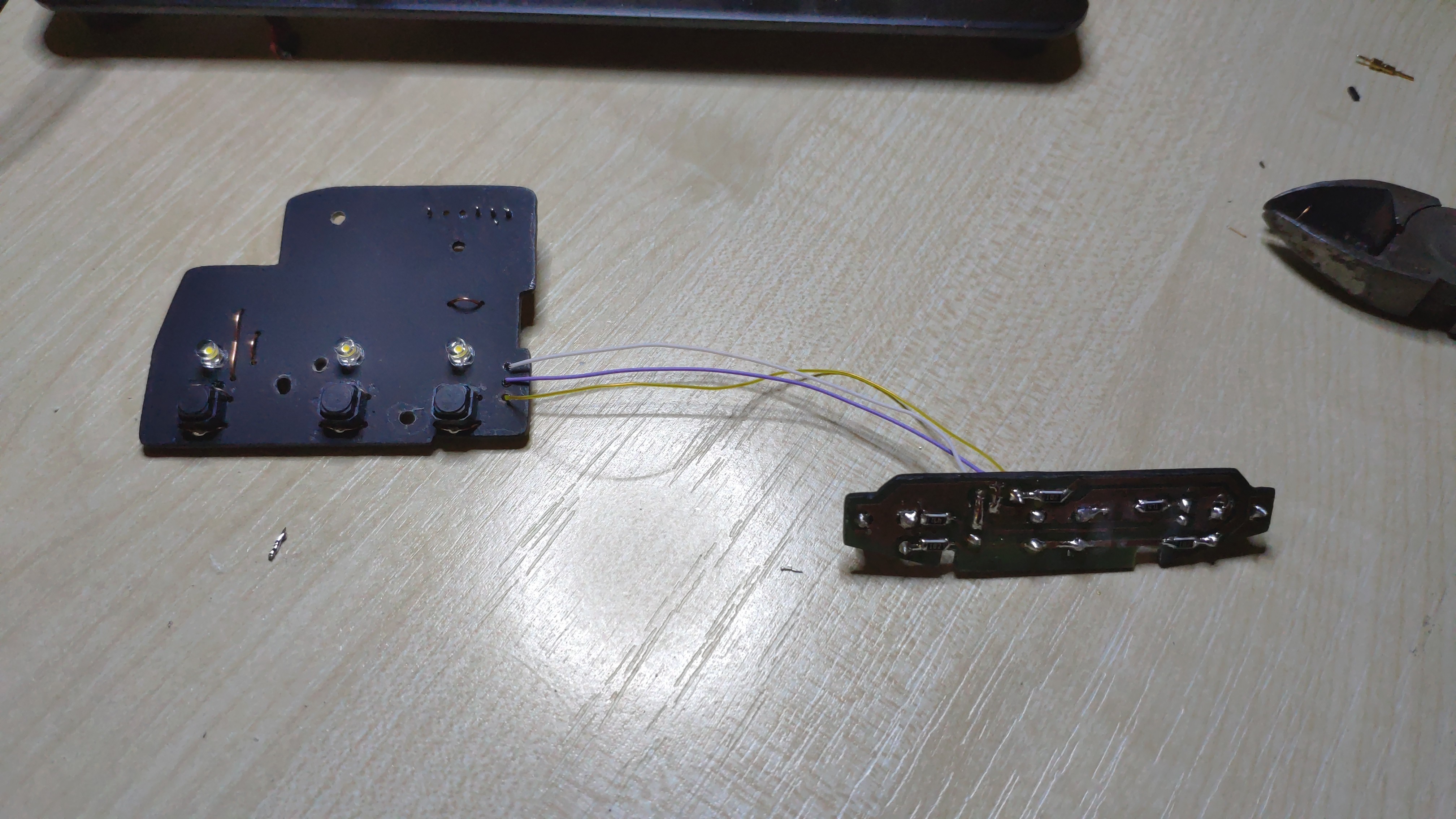
 Wires soldered in place of the stock microphone
 Reassembled front panel, microphone output going through a hole in the case
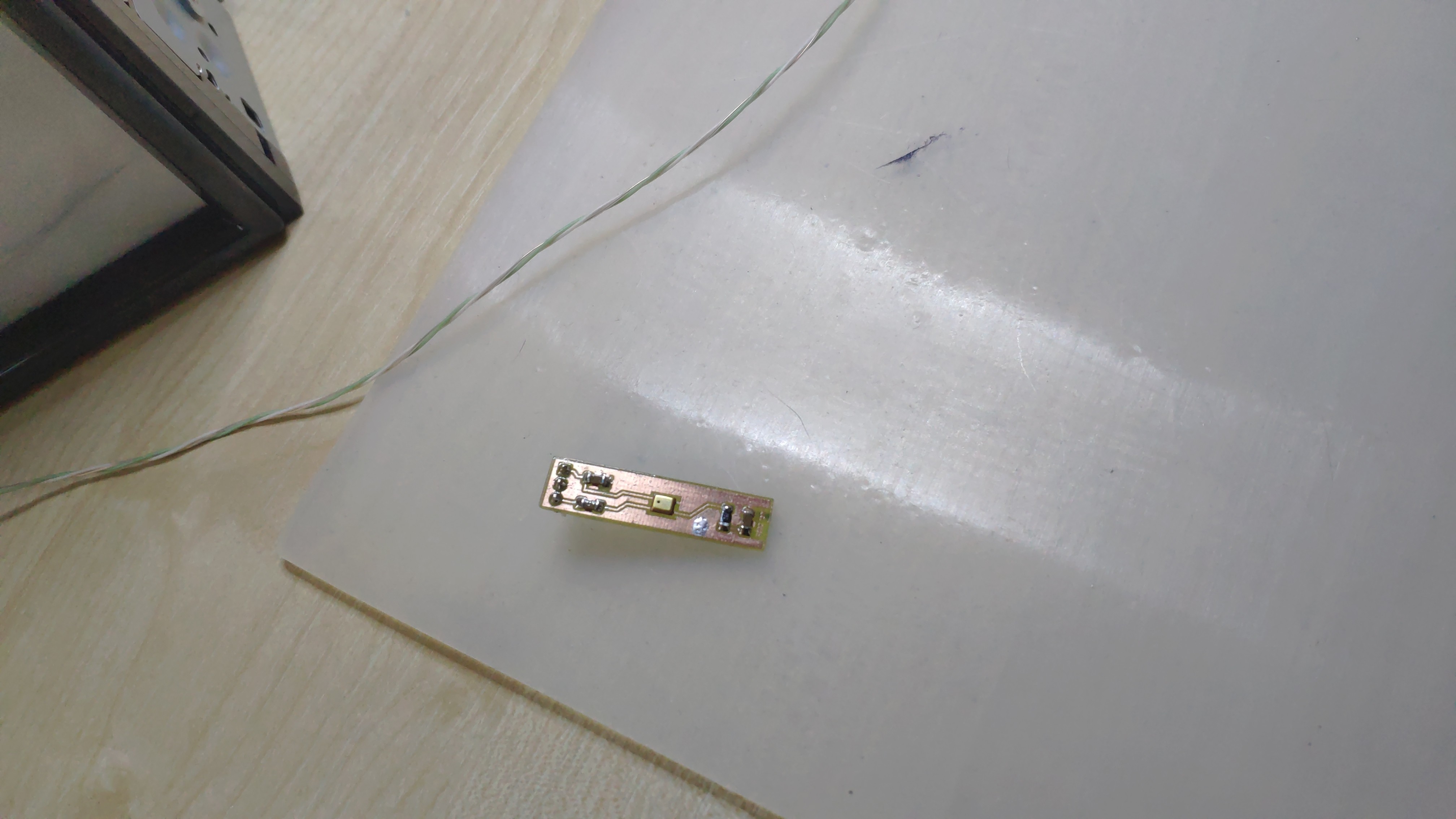 Helper PCB for replacement microphone (also SMD, with additional components to bump gain by 10 dB)
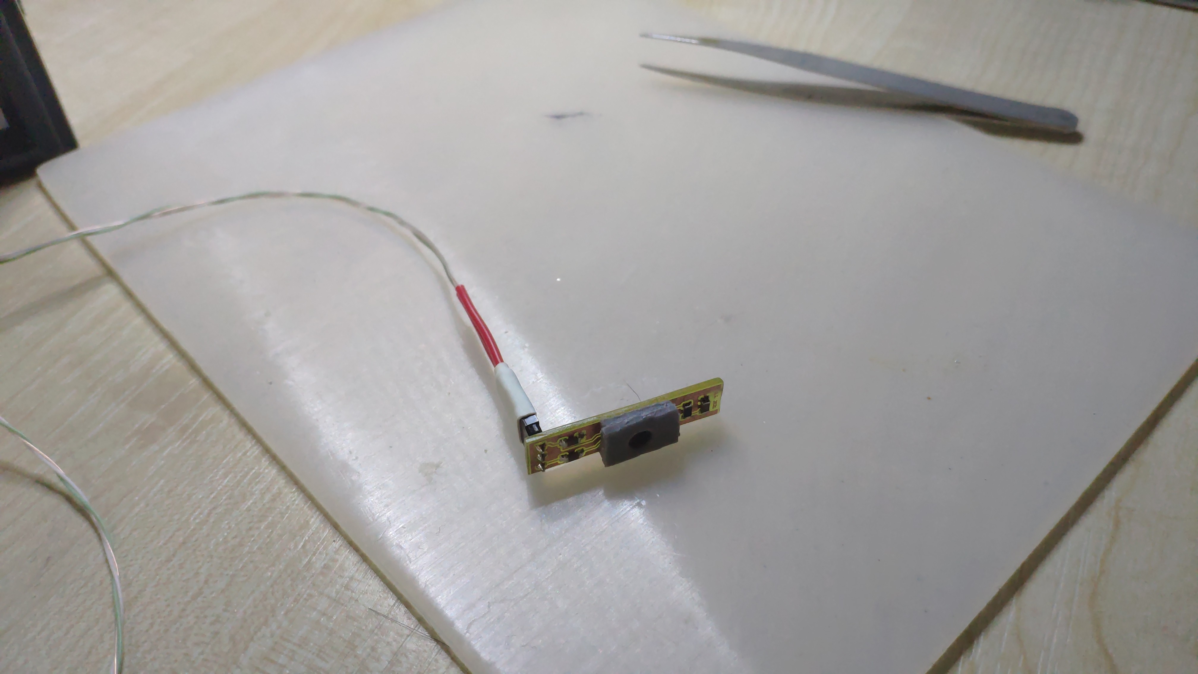 Microphone gasket for proper noise isolation (a double-sided foam tape)
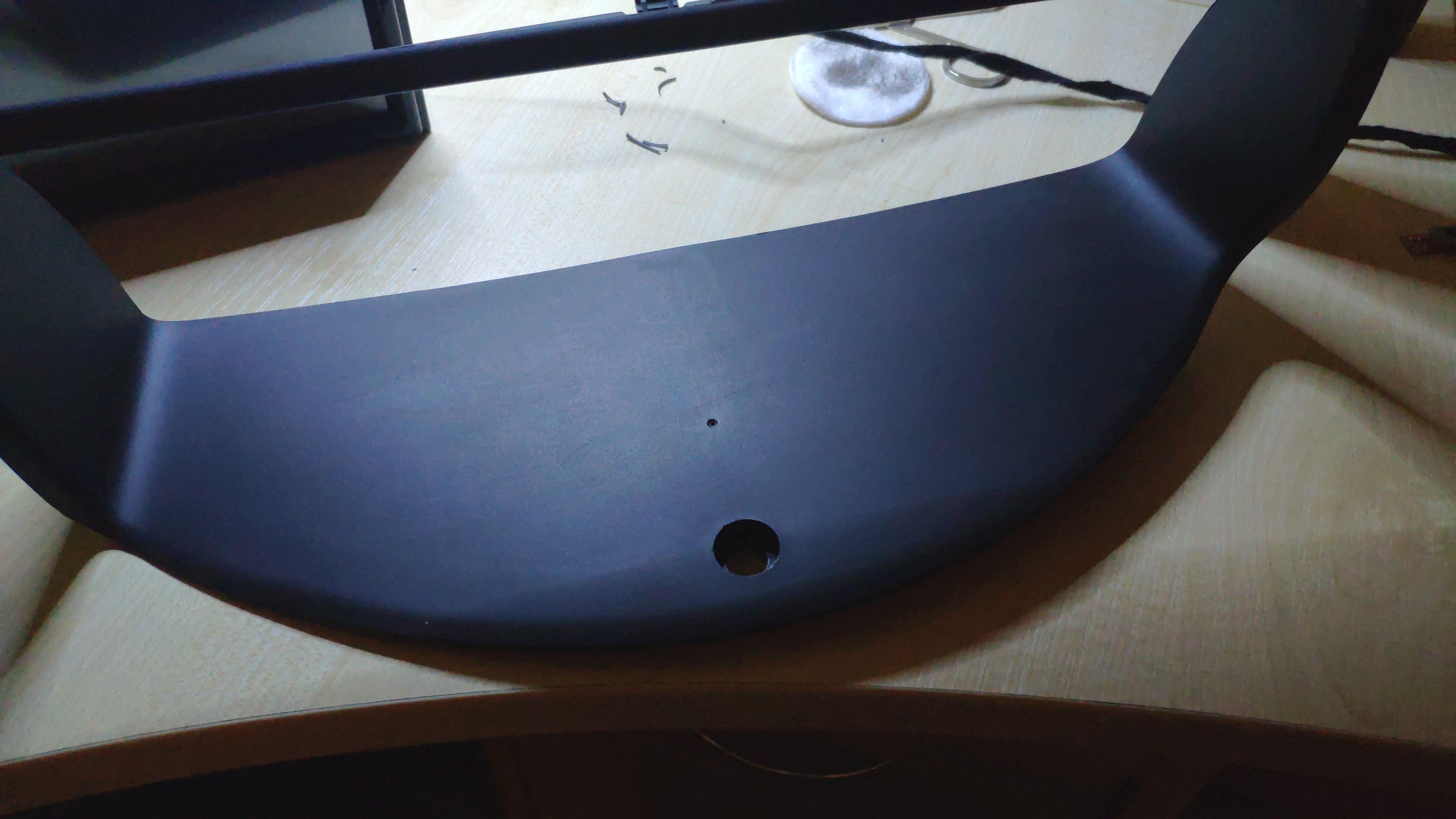 Hole for the microphone in the upper side of dash panel
Testing and further steps
As you can see, there were quite a few steps before Expansion Board could be functional. The necessary parts were the board itself and the wired remote. With those components I hooked up multimeter to the MCP42100 output and started writing software for the ATmega88.
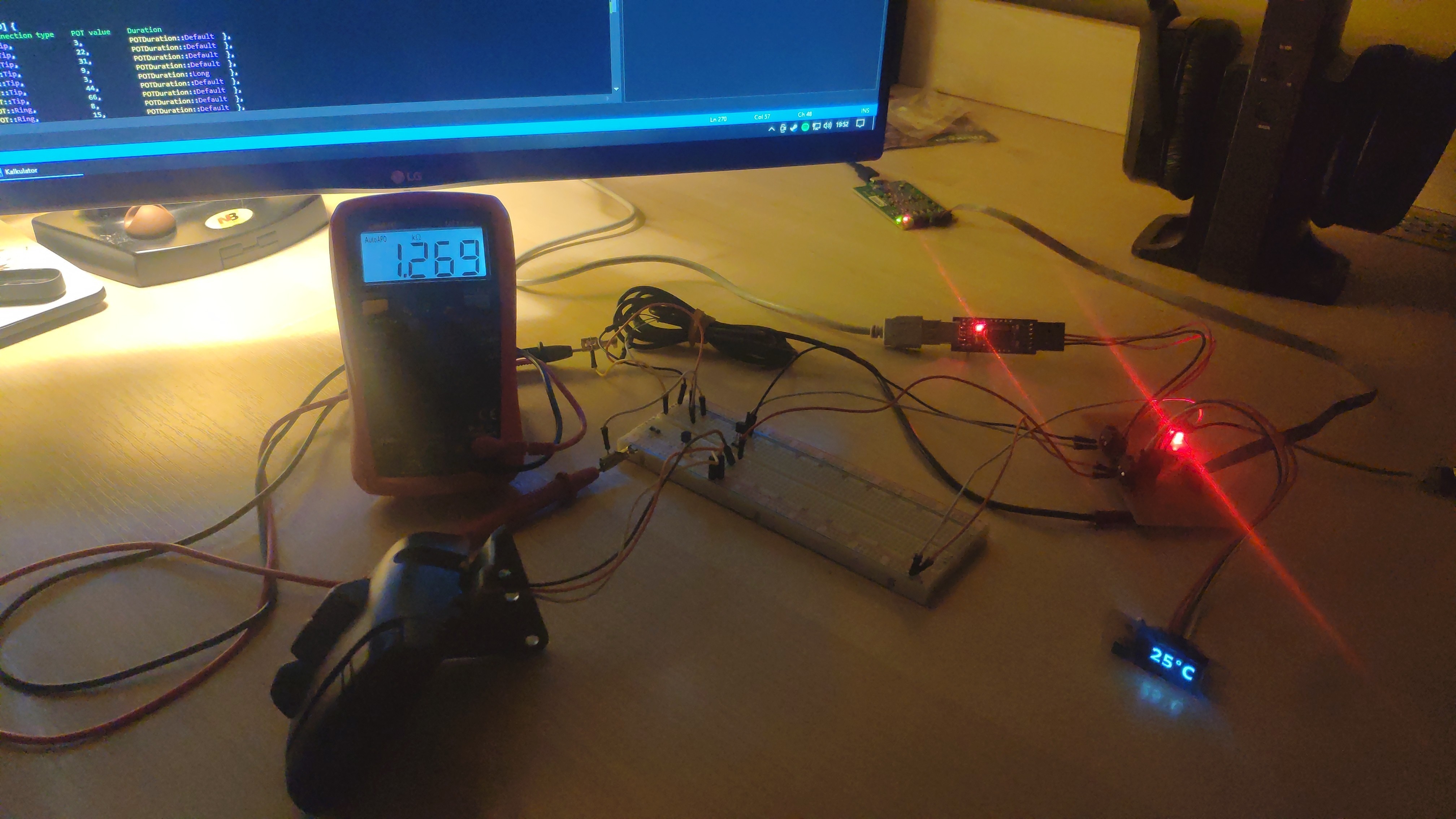 Early development setup
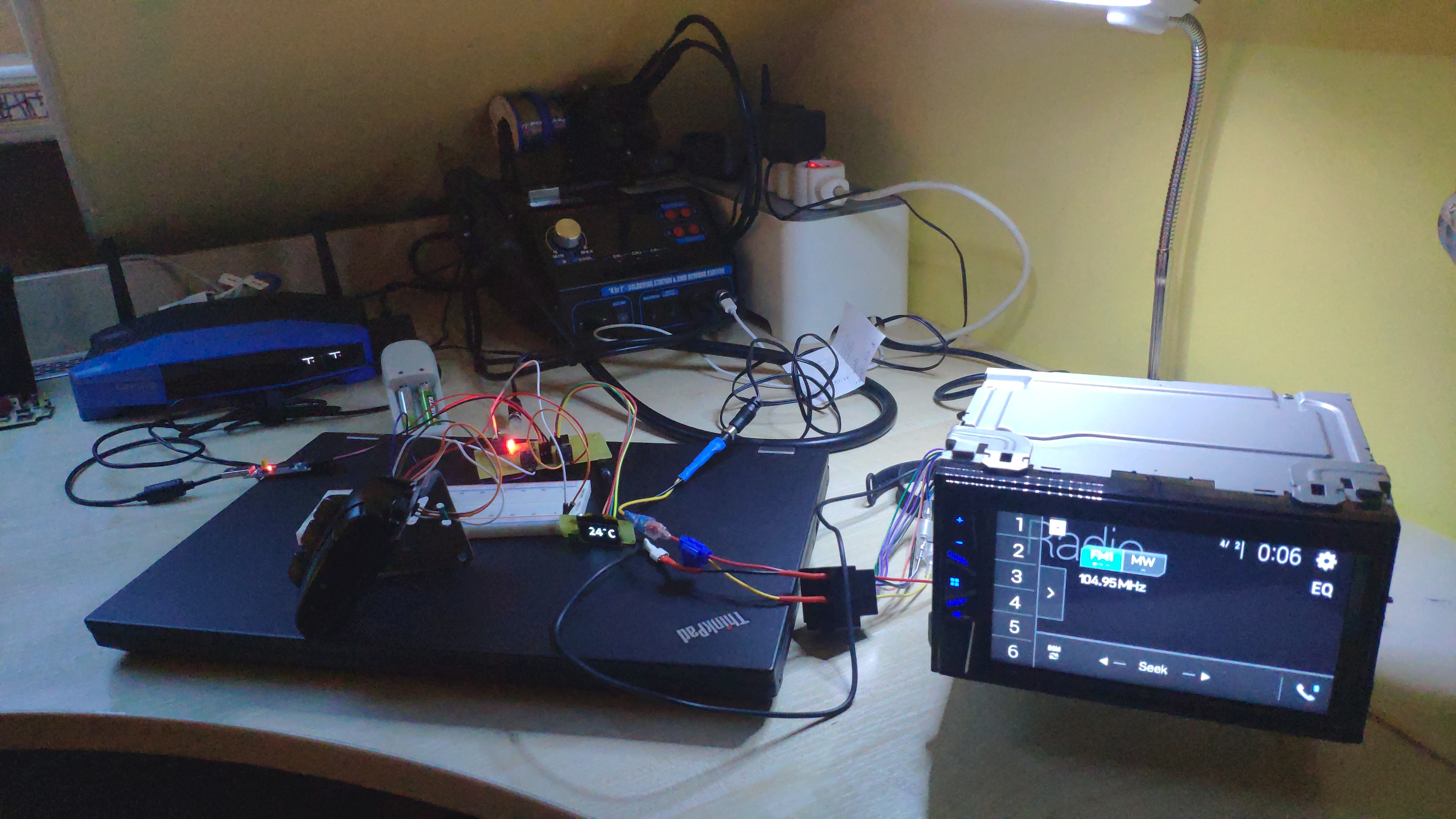 Late development setup
After few weeks of development, I had first revision of the working setup - “on the bench” everything worked like a charm, but as usual, working on the bench and working on the field are two different stories. When I hooked up the board, connecting it to +12 V and GND from the lighter, the board could not send proper signals to the radio - button press signals were going out randomly. For a while I thought the problem was in the Jack wire (I hand-soldered them), but after replacing it, issue remained. My second thought was that I somehow damaged the board while mounting the setup in the car - in order to test that theory, I disassembled it and got everything back home. To my surprise, at home it worked flawlessly… By a long shot, I figured there must be something wrong with the power source in the car - in the meaning that there may be a separation between front panel illumination, lighter +12 V, lighter GND and the power lines that are hooked up to the radio. To test it (and to be hones, have nice, proper power connections), I added extra wires to the ISO plug adapter with +12 V, GND and illumination signals.
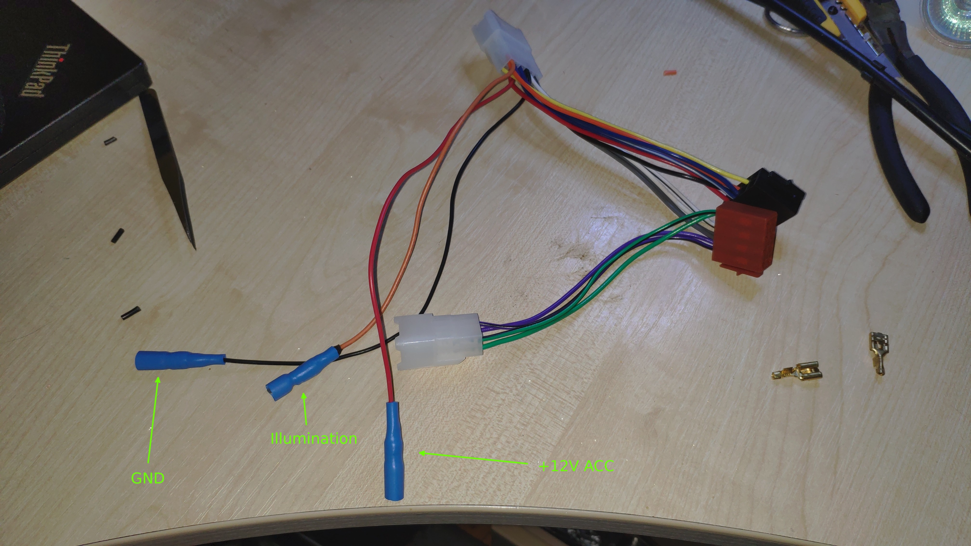 ISO plug adapter with additional output wires
Once modified plug and the rest of the setup was in place, the board started working without any issues. At the time of writing this post, I’ve been testing it for a few weeks now and so far there were no issues with it - every function each button has, works, temperature reading are accurate - long story short, a complete success. Except one tiny bit - I tend to drive a lot in polarized sunglasses. Imagine my surprise, when I saw that OLED display is also polarized - and the polarization is perpendicular to one in my sunglasses. In effect, I don’t see the temperature reading while in glasses.
I didn’t see that coming…