The project goal is to replicate a wired remote functionality with ability to distinguish short and long button presses, perform outside temperature readings and show it on OLED display. While prototyping a solution I also throw in the mix improvement to unit’s microphone (which had a very poor sound quality). In this post I’ll show project core concepts and components that will give you a basic idea about it.
Parts:
Building blocks
Primary function of the project is to create a wired remote control that Pioneer radio unit can understand. Because one of the requirements is that short and long button presses can perform different actions, input processing and output generation will be done by a microcontroller. Diagram below shows project key components and relationship between them.
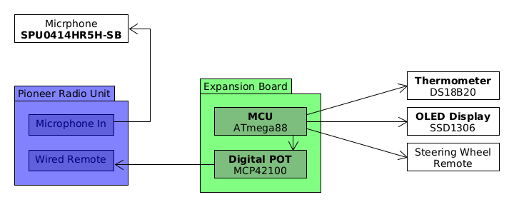
MCU
From a vast amount of microcontrollers available on the market I picked ATmega88 because I know it, I already had the tooling (programmer, toolchain) and it has enough features to get things done (SPI, TWI, general purpose I/O pins). Device is powered by a AP65111AWU-7 voltage regulator set to output 3,7V (I overdid it with resistors and end up with a little bit higher voltage, but it’s still acceptable) and clocked by external 4 MHz crystal oscillator.
There are three peripherals attached to the MCU:
MCP42100
A dual digital 100000 ohms potentiometer working on a SPI. This is the module that sends signals to Pioneer’s W/R 3,5mm Jack input. When MCU got a positive reading about button being pressed (and released), it will use this chip to set desired resistance on the output and keep it for a short period of time, emulating a button press event.
DS18B12
A digital thermometer with 11-bit resolution working on a 1-Wire bus. Stock radio unit had a feature of showing external temperature measured by thermometer placed behind a front bumper. With stock radio unit gone, this feature also went away and although outside temperature readings are not crucial, I thought it would be a nice addition.
OLED-AG-L-12864-03C-WHITE-0i96
A 0,96’’ OLED display with SSD1306 driver working on I2C bus (TWI). It’s responsible for displaying current temperature readings. I decided to use OLED panel because other display solutions would either be too big or the display’s backlight would make my dashboard a little bit too bright. Since the display will be showing at most five characters (minus sign, two digits, degree and Celsius characters), it is a perfect fit.
Steering Wheel Remote
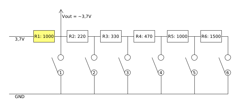
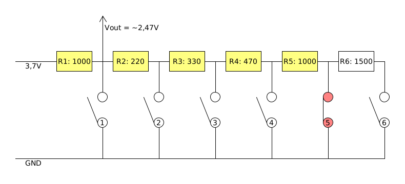
Stock wired remote is a digital device that works with AVC-LAN protocol. As designed board works with analog inputs, I had to replace remote internal PCBs with analog circuit and change the wirings behind the steering wheel to cut out signal lines from ECU and re-route them to the expansion board. Remote’s replacement PCB is fairly simple: analog signal is produced by a voltage divider arranged in a ladder where each button has a corresponding resistance value. When given button is pressed, ladder divides input voltage and by measuring a voltage drop, MCU can find out which button is currently being pressed. On following schematic you can see the ladder arrangement:
 No button pressed
When no button is pressed, voltage goes through resistor R1 without division - output signal will be close to input voltage. When switch number 1 (first on the left) is shortened, current will flow right to GND and in effect output voltage will be close to zero.
 First button pressed
Voltage divider starts dividing the output signal when next buttons are being pressed. For example, when switch number 2 is shortened, MCU will measure the voltage drop between R1 (1000 ohms) and R2 (220 ohms). Basing on Ohms Law, we can calculate:
 Second button pressed
Since resistors R2 through R6 are connected in series, same rule applies to the remaining buttons - Rb for voltage divider formula will be a sum of resistances in series up to the button pressed:
| Button | Rb resistance | Output voltage |
|---|---|---|
| 1 | 0 | ~ 0,10V |
| 2 | 220 | ~ 0,67V |
| 3 | 220 + 330 = 550 | ~ 1,31V |
| 4 | 220 + 330 + 470 = 1020 | ~ 1,87V |
| 5 | 220 + 330 + 470 + 1000 = 2020 | ~ 2,47V |
| 6 | 220 + 330 + 470 + 1000 + 1500 = 3520 | ~ 2,88V |
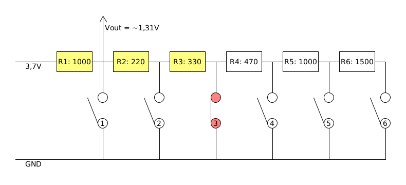 Third button pressed
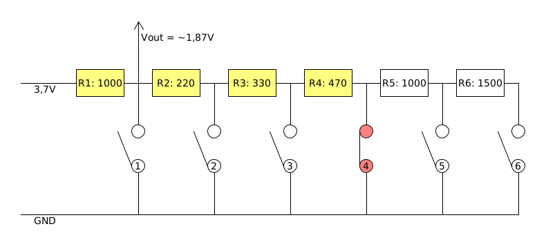 Fourth button pressed
 Fifth button pressed
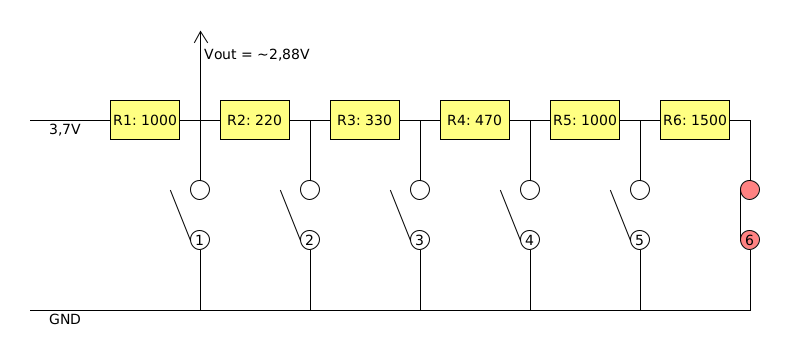 Sixth button pressed
You may wonder why resistors have different values - it would also work if every resistor had the same resistance. Values were calculated and picked to match standard resistor values to make voltage gaps fairly even. If you look closely at output voltage values, you may notice that voltage gap between each button is around 0,6V. Given that maximum voltage value is 3,7V and we have 6 buttons, we can calculate the gap as .
Below are plots showing output voltage values for each button. First shows voltage values for resistors with different values, second shows voltage values for the case where each resistor value is set to 1000 ohm:
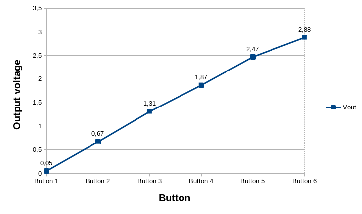 Output voltage for different resistor values
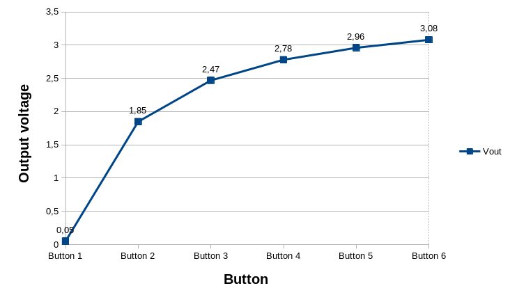 Output voltage for single resistor value
There’s a problem in the case where each resistor has the same value. Voltage gap between button 5 and 6 is only 0,12V - if we’re measuring this value with a 12-bit ADC, then it would give 819 and 852 ADC value readings respectively on a 0-1024 scale. With such a small gap, MCU would have a hard time distinguishing one button from another (keep in mind that there are numerous factors that makes those values fluctuate, like voltage jitter, interference, ambient temperature, button press duration or even button quality). Linear voltage growth for each consecutive button solves this problem.
Pioneer DMH-G220BT
The radio unit. It’s a 2-DIN AM/FM radio with Bluetooth support (audio playback and hands-free calls). Normally, there wouldn’t be much to talk about, but the unit has one major downside. Vendor placed microphone in probably the worst casing it could. Front panel has a small thru-hole that leads to a microphone and that’s fine, in general. Problem is that microphone doesn’t have proper isolation and its direction is toward the middle of the car. In the middle of the first row there’s a gear shift stick, not my head. That makes the microphone unusable because in order to be heard by the caller, I’d have to lean to the right side to talk directly to the microphone and the casing issues makes microphone performance unacceptable.
To show you what the problem with the casing is, let’s see how Pioneer designed the case:
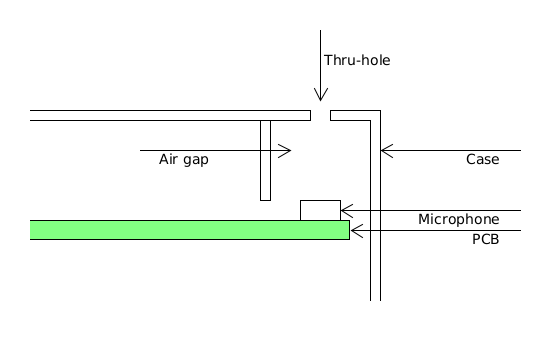 Simplified Pioneer case schematic with microphone part
Air gap between plastic case and a PCB containing the microphone degrades voice quality. Knowles SiSonic Design Guide describes this problem:
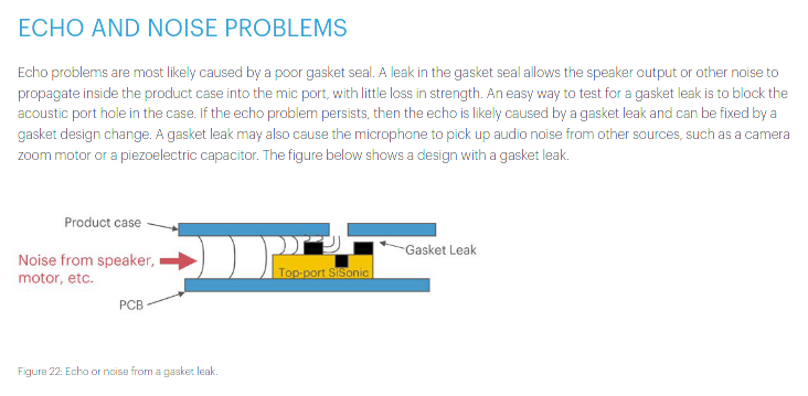 Echo and noise problems from Knowles SiSonic Design Guide
Problem could be solved by external microphone, unfortunately vendor didn’t provide any way to connect one. The fix was to replace the microphone with a wired connector and place it in a more convenient place - I decided that dashboard masking panel directly behind steering wheel would be a perfect place for it. Microphone replacement did help a bit with sound quality to the point, that most of the time caller can understand me, but audio quality still could be better. Unfortunately I suspect that the other end may be responsible - that is ADC on the radio unit itself.