Back in 2018, when construction of my new home began, I ended up driving to construction site almost every day - that was wasting approximately 1 hour every day just to drive back and forth. Because of that huge time waster and obvious reason that “things” gets “displaced” on construction sites, I’ve decided that I need some kind of surveillance on-site.
First and obvious choice would be some cheap IP camera, but given conditions under which camera would work, I needed to consider some prerequisites:
- power delivery: someone could plug out power cable and that would be pretty much it for surveillance, hence a requirement was backup battery power supply
- ability to store live feed in remote location: since there would be no way of accessing camera remotely (dynamic IP, firewall), camera would have to store live feed in remote location - i.e. private, publicly accessible server
- Internet connection: since I don’t have wired connection on-site, my only choice would be to use 3G - fortunately I already had a USB dongle and a card with 100 GB of mobile transfer per month already in place
- given that 3G connection can give low upload bandwidth, camera had to have option to customize resolution, frame rate, codec options (preferably variable bit rate)
- ability to capture in poor lighting / at night
After doing a little bit of digging I realized that already available solutions might cost quite a bit and not necessarily meet all the requirements / expected quality of service. Since I already had some parts lying around and to be honest - because it would be fun - I’ve decided that I will build my own camera. And so it began…
Hardware
Raspberry Pi Zero was my first choice, but due to some unexpected problems with power supply, which fried my board, I ended up using regular Raspberry Pi 2 I had in stock. I was already familiar with this platform, it runs under vanilla GNU/Linux distribution, has decent performance, hardware-accelerated H.264 encoding and most importantly - dedicated camera port.
Parts listing:
- Raspberry Pi Zero ($5) replaced with Raspberry Pi 2 Model B (in stock, $25)
- Waveshare Camera HD Night Vision H (~$40)
- ZTE MF820D 3G USB modem (~$20) replaced with TP-Link TL-WN722N Wi-Fi card (in stock, ~$10) and Huawei E5372 Wireless 3G router (~$13)
- Battery - AKUELL BT-02-108 12V 12Ah (~$30)
- Prototype circuit boards (in stock, ~$0.30)
- Main power supply with voltage regulator based on LM317T (~$0.25/piece) acting as regular power supply and a buffered battery charger
- Secondary power supply with voltage regulator based on LM2576T for 5V line (~$1/piece)
- Secondary power supply with voltage regulator based on LM2576T for 3.3V line (~$1/piece)
- 230/2x9V transformer (~$15)
- PCF8563 RTC clock (~$0.55)
- Fans, resistors, capacitors, coils, diodes, wires, connectors, LEDs (all in stock, around $20 in total)
- Case (~$7)
In total (discarding replaced parts - I had to pay for my mistakes ;) it’s around $165. Is it or isn’t it much for a camera? It depends - you probably could find a solution that would meet most of the requirements (though as far as I know, most products doesn’t provide sufficient backup power supply and means for providing Internet connection).
Raspberry Pi with camera module
Main device of the project. It’s small, supports I2C (so I could attach RTC), has little appetite for power, decent performance, dedicated camera port and a powerful support from software side - excellent choice for a home-made project, as thousands have already proven. And I already had a history with it…
Camera module - night vision version. It provides decent video quality at day and night, considering poor lighting and only 9W for artificial light source. This is a version with wide-angle lense, so there’s more area covered by it. Initial idea was to use 3 separate camera with dedicated multiplexer, but after some testing, I concluded that:
- hardware multiplexer has poor quality if you want to capture live video feeds from 3 cameras (frames were interlacing with each other) - I’ve written whole capture software basing on raspivid and I’ve managed to actually capture two simultaneous streams, but every few seconds, for a second, I got capture from wrong camera. I wasn’t able to make muxing synchronization to work.
- single video stream, H.264 hardware-encoded, 1280x720 @ 5 FPS, grayscale with quantization set to 20 and variable bit rate produced constant data flow with rates up to 1 Mb/s. For 3 cameras that would be 3 Mb/s at peak - that would create quite a data backlog (though that would be extremely rare case). Due to mobile internet connection constraints (when I exceed data limit, my transfer rate goes down to 1 Mb/s), this was another deal breaker for 3 cameras setup.
Having those two problems that couldn’t be simply solved, I abandoned this approach and went with a single camera setup (but I still feel a little bit unsatisfied).
Internet connection
My first approach to Internet connection was to use 3G dongle, in that case ZTE MF820D. As expected, it turned out that Raspberry Pi cannot provide enough power to the device - it was shutting down as soon as it tried to connect to cellular network. That forced me to provide means for powering dongle externally. Since I’ve been building my own voltage regulator specifically for 5V line, it seemed easy enough, right? Just put a 5V line into the USB cable, solder USB port onto the board, and voila - modem should be stable… Not quite. Because I’ve been using prototype board, connections were rather crude. Elements placement, along with loose wires didn’t help either - there was just too much noise around the device. At first modem was pretty stable so I considered that this part is done, but once I put everything together and ran stress tests, it turned out that modem couldn’t last 2 days without locking itself up.
Simplest solution? Just reset the device! That should work, except that modem had external power supply, so I couldn’t just power-cycle it. Resetting USB hub inside Raspberry Pi? The device didn’t show up after reset. So I thought that since I have a power signal from Raspberry Pi over USB port, I could put external power for modem through MOSFET transistor and if there’s no power on USB port, the device would reset. And although this could solve the power-cycle problem, it didn’t help the modem - it was still locking up, only physical reconnect was helping out. Because it’s a no-go for a surveillance device to have such instability issues, I’ve decided to ditch USB dongle and buy Wi-Fi router with 3G capabilities. I found used Huawei E5372 on auction and bought it for 13 bucks. It has an internal backup battery, supports 2.4 and 5 GHz networks and pretty much just works out of the box. Although it may seem like a workaround, it actually turned out to be a better solution - placement of the camera would determine where 3G antennas would be. With mobile router, I could put it in a place where I have best signal and still be able to serve Internet connection to camera wherever it would be placed, within Wi-Fi range.
Power supply
One of the most important features of the camera was to have a good backup power supply that will be able to work outdoors. I could consider an existing UPS solutions, but they weren’t meant to be used outdoors. Another reason for my own supply was that I could enclose it in one case with the rest of the hardware.
I started by estimating how much power whole hardware will draw and how long power outages I could expect - it’s a construction site, everything is out in the open, someone could damage power lines or just plug the camera out. I estimated (very roughly) current draw for each component (assuming maximal load):
- Raspberry Pi 2 Model B: ~400mA @ 5V (2W).
- Camera: (~ 200mA @ 3.3V - 0.66W) with 3 IR diodes, each rated at 3W (9.66W in total).
- Wi-Fi card: ~40mA (0.2W).
- PCF8563 RTC clock: ~10mA (0.05W).
- Fan for LM317T voltage regulator: 100mA (0.5W).
That gives 12.5 Watts. Knowing that (and current ratings) I estimated how much power will be lost on voltage regulators:
- First LM2576T has efficiency around 77% (per datasheet). For 5V line I estimated that current draw will be roughly at 700mA (3.5W). Given that, regulator will draw 4.55 Watts of power, and that means it should dissipate 1.05 Watts of power as heat.
- Second LM2576T that will regulate 3.3V line have lower efficiency, but it’s not given in datasheet, I assumed it was at 72%. Current draw for this line was estimated as 2.74A (9W). If regulator outputs that much current, with efficiency at 72%, it will draw 12.5W and would dissipate 3.5 Watts as heat.
After taking into account power lost as heat (4.55W), I end up with 17.05 Watts of power. Having a battery with 12Ah we can calculate:
12V x 12Ah = 144Wh
144Wh / 17.05W = 8.45h
That gives us more than 8 hours of constant work on battery. Bear in mind that this is just theoretical and very rough estimation! On one hand, most components won’t work at it’s peak current rating, on the other hand, battery most probably will be either degraded or little bit discharged and won’t have perfect characteristics that manufacturer declares, not to mention battery’s own efficiency. Even so, we can safely assume that picked battery will withstand at least a couple of hours of video streaming.
Last component is the buffered power supply circuit based on LM317T. Given that input voltage is 20V, output power is 17.05W and output voltage is set to 13.65V, I can calculate that output current for this regulator would be 1.2A - almost at device’s limit, which is 1.5A. Just for curiosity I’ve also calculated how much power will be wasted as heat on this last circuit:
V(diff) = 20V - 13.65V = 6.35V
P(loss) = 1.2A x V(diff) = 7.62W
So, in total, power consumption should be 24.67W. Below are results from live readings with IR diodes off and on:
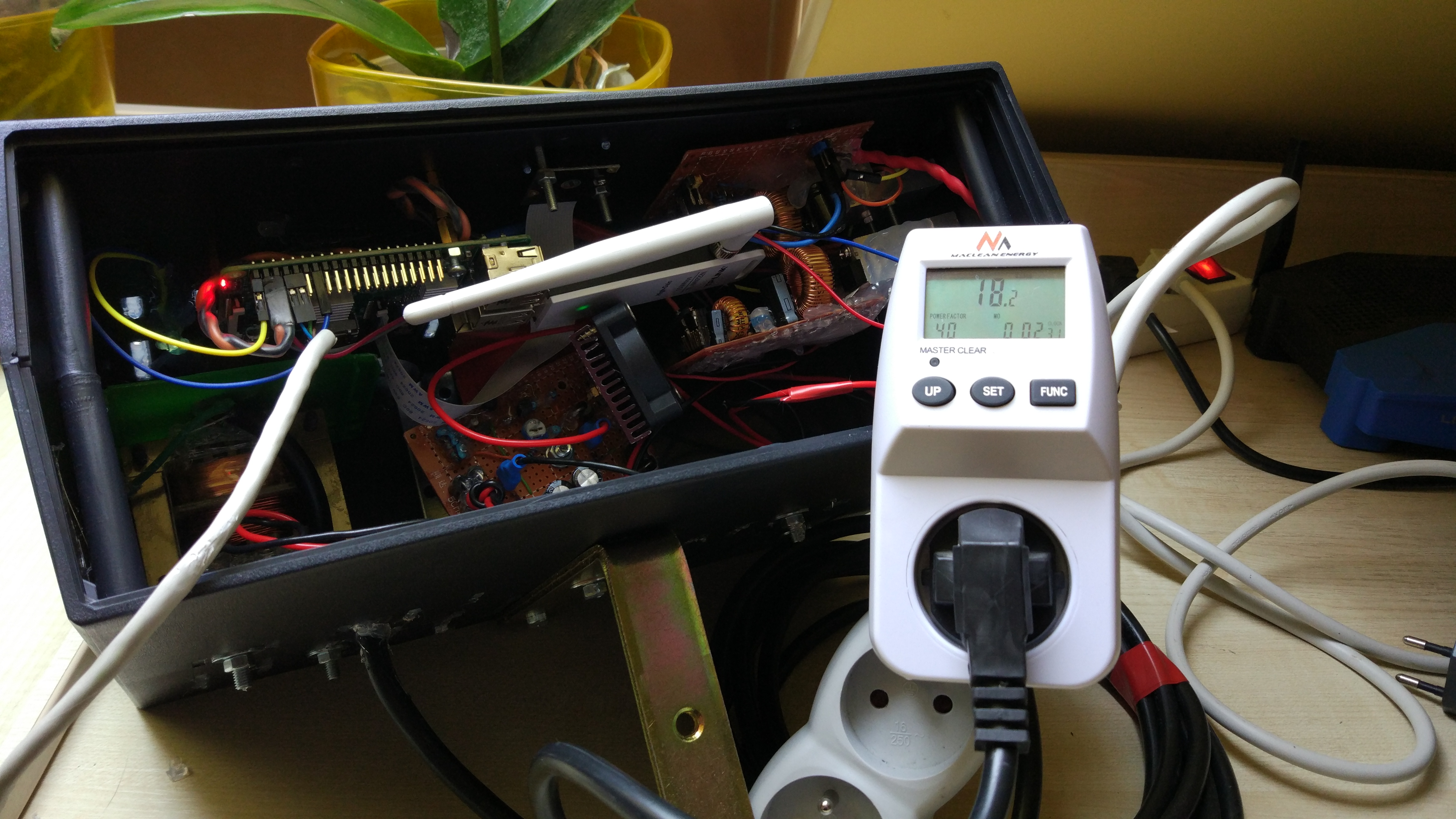
Without IR diodes, power consumption is a little bit above 18W.
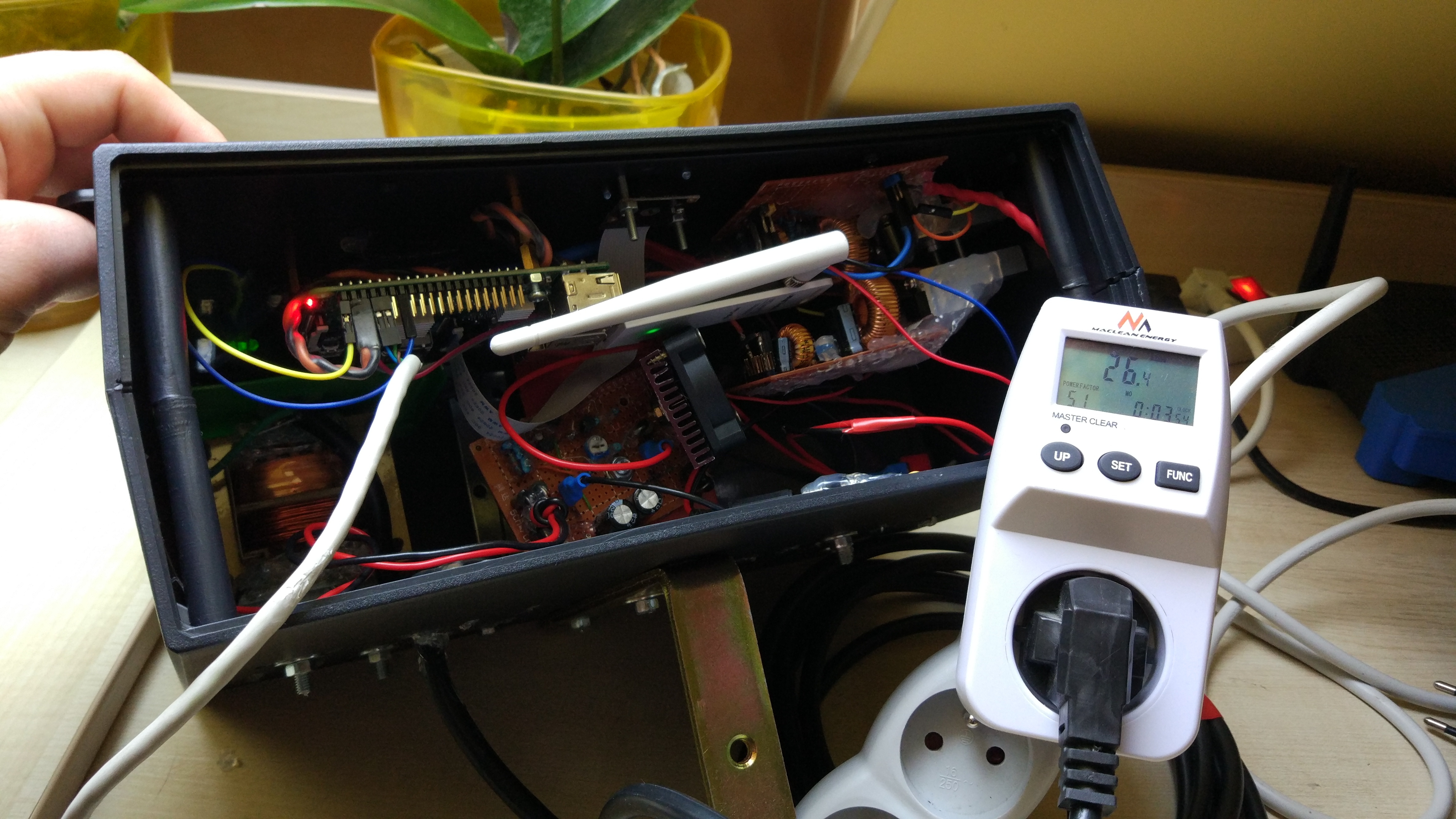
With IR diodes on, power consumption is around 26W. Given estimates that didn’t take into account loses at passive components (resistors, diodes) and transformer (plus dissipated heat by it), live readings goes quite close to estimated value.
As for schematics, 5V and 3.3V voltage regulators circuits are based on standard application schematic from datasheet. As for the buffered power supply that is used to either supply power or charge the battery I used article from "Elektronika dla wszystkich" 10/98
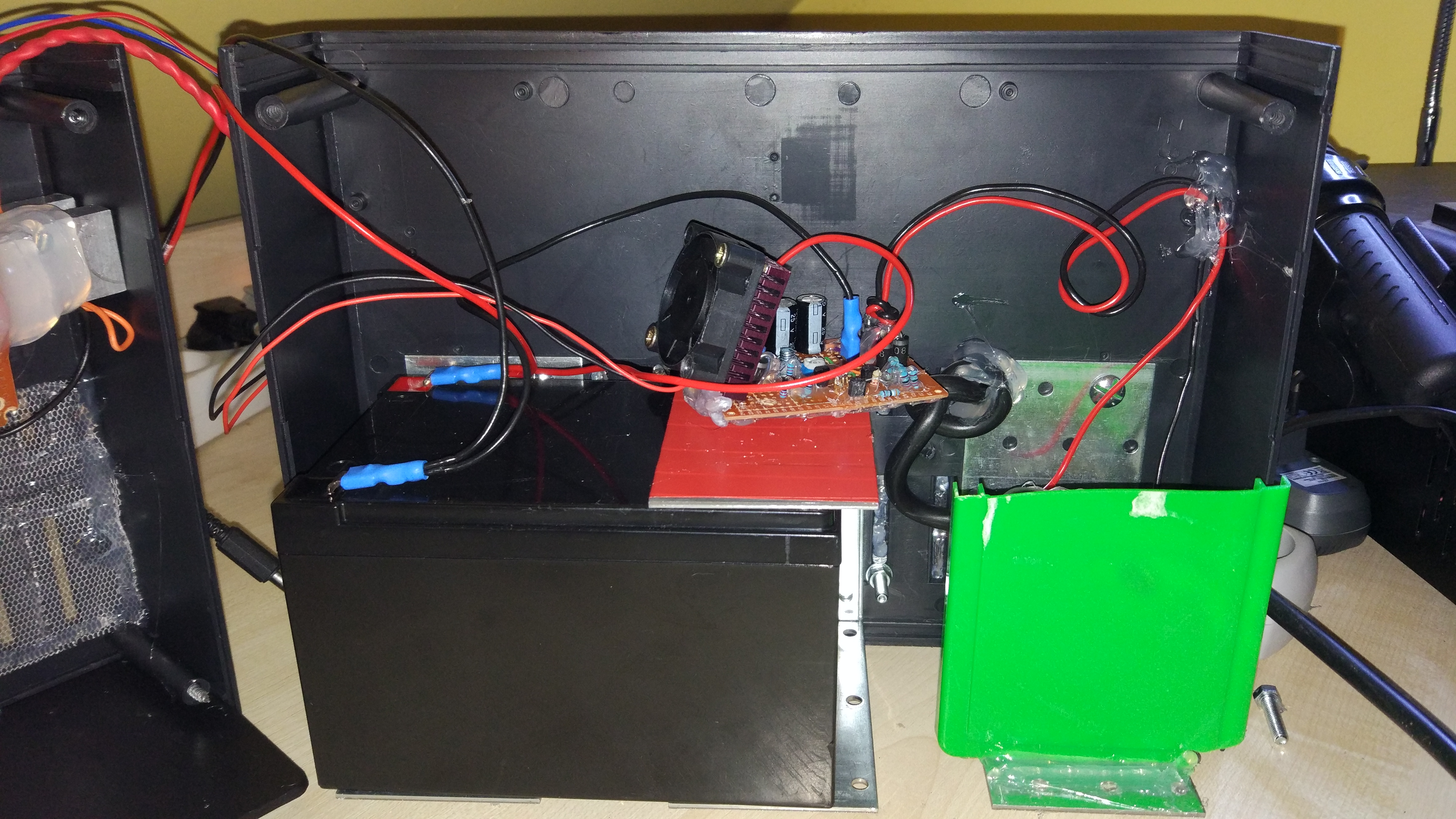
Case
There are two fans in the case - one on LM317T’s heatsink, as this component will dissipate most power as heat and if being too hot, could limit maximal rating of output current (it has thermal protection built-in) and on case itself, as inside there’s a battery that cannot be sealed completely off - case must be ventilated. Smart routing could probably save design from having two fans, but I decided to be lazy in that matter.
In theory, case should be hermetic or at least water and splash resistant - but because battery is inside the case, it must have some sort of ventilation. Due to that reason and prices of professional outdoor cases, I went with a standard indoor-use plastic case that I’ve reinforced with metal plates that holds the battery (it weight quite a bit) and closed most holes with hot glue - it should protect the case from rain and snow.
Tip about power lines
During most of my tests I was struggling with random resets, messages from kernel about under-voltage being detected, etc. I always thought that I was just physically messing with some wires and due to rather poor wire connections, I just shorted or disconnected power lines for a second and that’s that. Test was running at night? Cat yet again wanted to chew on power cable. But as I was getting closer to the end of the work on hardware, I still couldn’t get resets to go away - that was the moment when I realized there’s something really wrong, so I started searching. What I did prior to finding the right solution:
- checked pins connections,
- checked if pins are soldered correctly,
- re-soldered pins anyway,
- checked wires and theirs connectors,
- checked filtering capacitors at power supply inputs and outputs,
- replaced those capacitor with new ones,
- thickened power lines on circuit boards,
- re-routed wires to minimize interference.
And nothing worked - I still had random resets. So I gave up for a while until anything new would pop up into my mind to try out. And I waited… One day I was watching this guy on YouTube talking about twisting power lines and why you should do it and then it hit me - all my power lines were happily dangling around - and in close proximity I had Wi-Fi card, Wi-Fi router, AC power lines, transformer and bunch of invisible noise that could affect my circuits. So I went with his advice and twisted all power lines - and that was it, I got one week uptime without any more efforts.
Lesson learned - always twist your wires in order to eliminate external noise.
Software
Requirement was simple - capture video from camera, encode it, encapsulate it in some sort of container and send over the network. All that could be done with stock Raspbian image, but I decided to choose another path - build my own Linux distribution!
Operating System
Building Linux distribution by hand is hard, really, really hard. Tons of packages that would have to be built is just enormous. Luckily there are tools that help with that process. One notable example is Yocto. Unfortunately I don’t know this framework and since time was a pressing matter for this project, among other things, I decided to go with what I already knew - Buildroot.
Buildroot is a set of Makefile scripts that help you with:
- picking right settings for your platform: compiler, Linux kernel, init system, filesystem layout, target packages,
- compiling every aspect of OS in the right order,
- packaging result OS in suitable format (in this case, SD card image).
Raspberry Pi as a platform has very good support in Buildroot, so there was no problem with starting off. Once I built my first image and tested that it’s running good on target device, I started customizing.
First thing I did was to build my own toolchain. Although Buildroot provides it’s own toolchain for given platform, once you clean your build, it also cleans the toolchain - that’s a serious time waste. For building toolchain I’ve used a tool similar to Buildroot itself called crosstool-NG - it helps with building GCC compiler (8.2), binutils, standard C library (uClibC-ng) and other required tools. With easy to use ncurses Linux-like menuconfig, you can customize most of toolchain aspects, pick binaries version, minimal Linux kernel support, supported languages, features, etc. I went with this config - based mostly on defaults, with options that were mostly required by Buildroot.
Once I had a working toolchain, I’ve configured Buildroot to use it, rebuilt system image, ran stress tests and after everything seemed to be working stable, I started customizing packages. First, I wanted to have the most recent versions of packages - most importantly - FFmpeg, rpi-userland (contains raspivid binary) and rpi-firmware. As for former packages there was no problem - it just needs an updated git commit values, FFmpeg was harder, because Buildroot was sticking to 3.x release, where latest one as of time of writing this is 4.1. After patching Buildroot patches and adding some of my own, I ended up with the most recent FFmpeg package I could get.
After selecting needed packages, I focused on system’s init system. By default Buildroot uses Busybox as it’s init system - and that’s a good choice most of the time. But as I was experimenting with different approaches, I quickly decided to give systemd a go - mainly due to it’s powerful unit system, it’s really neat and easy to write services in systemd. And so I went with that choice for a while… Until I started actually measuring how much time systemd is wasting on, well, itself. Obvious choice would be to minimize the number of services that device wasn’t gonna use anyway, but default systemd setup in Buildroot already did a good job with that. From my measurements systemd was taking more than 30 seconds to spawn login prompt. It was using NetworkManager to establish network connection. I thought that I could live with that, but it just couldn’t let me go. My inner frustration with that time waste was bigger than reluctance to rewrite all services to another init system (and write new ones that currently were covered by systemd). I went back to Busybox - and, coupled with connman, from a 30+ seconds startup it went down to whooping less than 5 seconds for login prompt. Last time I measured Raspberry Pi’s performance was back in 2013 when I was still at university. Back then systemd wasn’t a viable choice for embedded systems, it seems it’s still not in 2019.
My Buildroot fork with raspberry-cctv_defconfig and other customization is available on github.com.
Capture software
One may say - obviously, motion! Well, I didn’t. My initial concept with 3 cameras basically excluded it from the start. Once I realized that only one camera will be in place, I already had a working prototype based on raspivid + FFmpeg - that’s one. Second reason is that although it makes sense to use motion to detect movement, this detection can be faulty and CPU consuming - since I was going for power efficiency, post-processing should rather be done somewhere else. When Raspberry Pi 2 Model B is idling, it consumes roughly 220mA, but it goes up to 400mA when it’s at full load. On the other hand, Wi-Fi card is consuming 40mA - given that H.264 encoding is hardware-accelerated, I would argue that constant data transfer will consume less power than constant movement detection - but to be honest, that’s just my estimation, not actual measurement.
If motion is out of the question, what can be done with raspivid and FFmpeg? Plenty. Raspivid is probably most advanced software that can set various camera parameters - I was going for Variable Bit Rate (VBR) and this application is able to do exactly that. With VBR and 4 FPS I get funny 30 KB worth of video stream per second for mostly still images and up to 70 KB for all-over-the-place movement. That’s under my minimal upload bandwidth constraint of 128 KB/s - all good so far.
Sending a video over the network is a problem in itself. FFmpeg supports HLS standard and it supports writing output files in remote location - just what this project needs. Except the fact that once there’s a network outage, FFmpeg doesn’t buffer much of that video, instead it just discards backlog data and gets only newest frames - that’s unacceptable. If I cannot rely on FFmpeg capabilities to send video to remote location, then I had to come up with something else - so I wrote a simple C++ application that does number of things:
- sends video to remote location,
- keeps persistent connection to the server (it’s important because we don’t waste bandwidth and resources for establishing connection, HTTPS handshake, etc.),
- keeps a backlog of video material - even hours of material can be kept on persistent storage and send later, if we have enough throughput.
With this application I’ve solved FFmpeg’s problem of sending files over the network, but I still needed FFmpeg package. Raspivid produces raw H.264 video stream, but that data cannot be safely sent over the network. Since I decided to use HLS protocol, files had to be segmented into smaller fragments (10 seconds) and encapsulated in some kind of container, in this case MPEG-TS (Transport Stream) - it’s a widely used container, I guess mostly in DVB-T/S. Container maintains essential information about the stream and contains data that makes segments error prone. In addition, after encapsulation, segment files can be played by ordinary web browser.
In summary, capturing software contains three components:
- raspivid for video capture,
- FFmpeg for stream encapsulation,
- camera_streamer for sending video segments over the network.
Server-side support
Server that will receive segment files must be properly configured and be publicly available. I used vanilla nginx with PHP-FPM - tandem that I’ve been using for more than 5 years and it didn’t let me down once.
Camera Streamer project expects server to support PUT method, we can get it done by enabling WebDAV module inside nginx:
location /camera {
    # ...
    client_max_body_size 10m;
    create_full_put_path on;

    dav_methods PUT DELETE;
    dav_access group:rw all:r;
}
And that should be it for the web server. But putting segment files on the server isn’t exactly usable - we still need to do some stuff before we can use them.
First is viewing - I could get each segment and play it i.e. in VLC, but that’s just too much overhead. Instead, I’ve written a PHP script that will glob video’s root directory, group results, glob once more, this time for video files for given date and produce m3u8 playlist from found files. Having a playlist, we can simply point any player to that location and enjoy live stream from our camera!
But here arises another problem - storage. TS files for 24 hours of capture can take as much as 4 GB of space - that’s a lot. What could be done with that? Each segment contains I-frame and each segment is 10 seconds long - that’s just not efficient. I could use FFmpeg one more time to simply concatenate segment files - but putting them all into one file won’t reduce overall size. I cannot get away with re-encoding the material. And if I’m forced to re-encode it, I might just as well use more efficient codec - here H.265 comes into place. 24 hours of video that takes ~3 GB as segment files after re-encoding with H.265 takes just 400 MB, which is far more storage space friendly. Encoding on 3 threads is done with x2 speed (i.e. a 4 FPS video is processed with 8 FPS speed) - enough to encode one day’s worth of video in less than actual day and to keep encoding machine responsive.
All server-side scripts are available on github.com.
Results
I’ve been testing camera for more than two weeks now and I’m more than happy with the results. Video quality is even better than I’ve expected, I’ve managed to keep power and bandwidth constraints, all the features I wanted are up and running - I consider it a success.
Below is a sample video fragment from tests (re-encoded for story purposes):
… and some photos of the device itself:


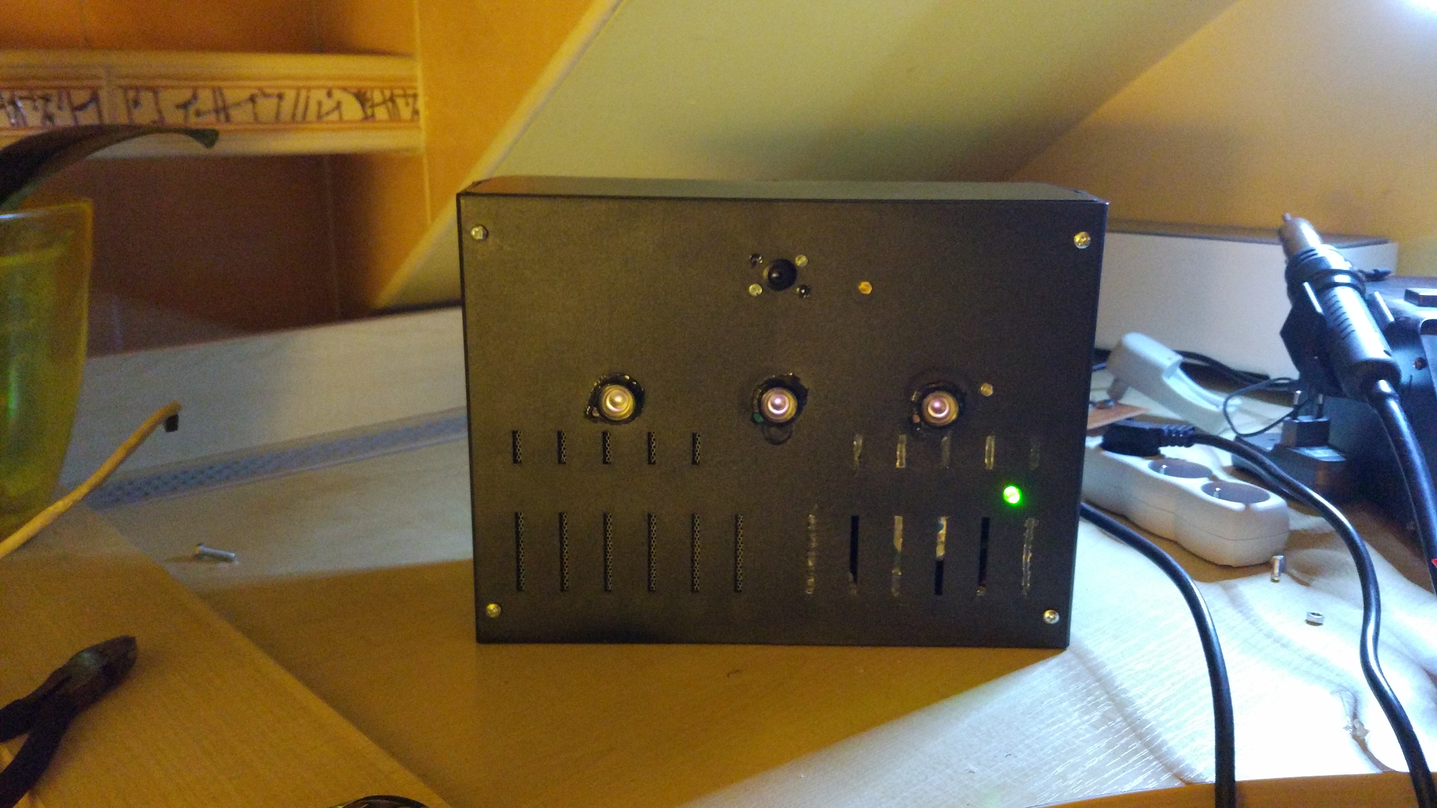

I started working on this project around the summer and ended it at the beginning of 2019 - I’m certainly not happy how long this project took, but would I do it again? Certainly! I’ve learned a lot about video processing, circuits (power supplies especially) and I had tons of fun while doing it!